Introduction
An X-ray framing camera based on a gated microchannel plate (MCP) is an essential diagnostic instrument in various fields including inertial confinement fusion (ICF) studies, Z-pinch experiments, and laser plasma physics [1-8]. Such cameras use a microstrip transmission line photocathode (PC) deposited on the MCP surface to transmit a short gating pulse [9, 10]. Temporal sampling of the signal is obtained while it is synchronized with the gating pulse [11, 12]. The temporal resolution of such a camera is limited by the transit time spread of electrons traversing the MCP channel pore [13-15]. When the camera consists of an MCP with a thickness of 0.5 mm, the temporal resolution ranges from 60 to 100 ps. In ICF experiments, the temporal resolution of such a camera is insufficient for acquiring a detailed history of implosion with 100–200 ps duration [16-18]. A faster camera is required to accurately characterize the implosion performance [19, 20]. Recently, Hilsabeck et al. developed a dilation X-ray imager (DIXI) with pulse dilation technology [21] and achieved temporal resolution higher than 10 ps [21-25]. The temporal width of the electron beam generated by the PC was dilated up to 50 times in the 50 cm drift region to achieve a high temporal resolution. Because of the long transmission distance of the electron beam in the drift region, an electronic optical system is required to image the electron beam from the PC onto the MCP to achieve a high spatial resolution. In the DIXI, four magnet coils were employed to achieve a spatial resolution of 510 μm for the Au PC [21, 22]. The single-line-of-sight camera developed by Nagel et al. used a Cu winding outside an evacuated drift tube to produce a magnetic field. A spatial resolution of 35 μm and working area with dimensions of 25.6 mm × 12.8 mm were achieved [26, 27]. Another 4 ps dilation framing camera used a short magnetic lens to image the electrons, achieving a spatial resolution of approximately 100 μm with a magnification ratio of 1:1 [28]. However, variations in spatial resolution within the working area have not been reported for dilation-framing cameras with short magnetic lenses. Generally, the off-axis spatial resolution is reduced because of the field curvature of the electronic optical imaging system of a camera that uses a short magnetic lens, which limits the working area and spatial resolution of the camera. Combined magnetic lenses were used in our framing camera to correct for the field curvature. Such magnetic lenses are frequently used to observe electron Moiré patterns or achieve high imaging quality in electron microscopes and streak cameras [29-32].
In this paper, an ultrafast framing camera with pulse-dilation technology and combined magnetic lenses is presented, and an X-ray diagnostic experiment is described. Four magnetic lenses were combined in the camera to reduce field curvature, and a spatial magnification ratio of 1:1 was designed. The temporal resolution of the camera was measured using a femtosecond laser and fiber bunch. The electronic optical imaging characteristics of the camera, such as the spatial resolution, field curvature, and sensitive area, were also analyzed. Furthermore, the camera was used to detect the X-rays produced by a terawatt laser targeting system.
Camera parameters
The ultrafast pulse-dilation framing camera consisted of a pulse-dilation device, an MCP imager, a combined lens imaging system, and a pulse generator; its schematic and photograph are shown in Figs. 1(a) and (b), respectively. The pulse dilation device included three microstrip X-ray PCs, an anode mesh, and a drift tube. The PCs were developed by coating an Au film with thickness of 80 nm onto a (C8H8)n film. Each PC was 12 mm wide, with a gap of 10 mm between two neighboring PCs. The PCs converted the X-rays into electrons and functioned as a microstrip transmission line to transmit the dilation electric pulse. The anode mesh was mounted 1.8 mm from the PC and connected to the ground. A high direct current (DC) voltage was applied to each PC strip overlaying the dilation pulse, which provided a varying PC voltage. The energy of the electrons arriving at the mesh was obtained by varying the PC voltage. An electron emitted from the PC earlier possessed higher energy and speed than those emitted later. Hence, the electron energy spread was obtained, resulting in temporal magnification of the electron pulse in the 550 mm drift tube.
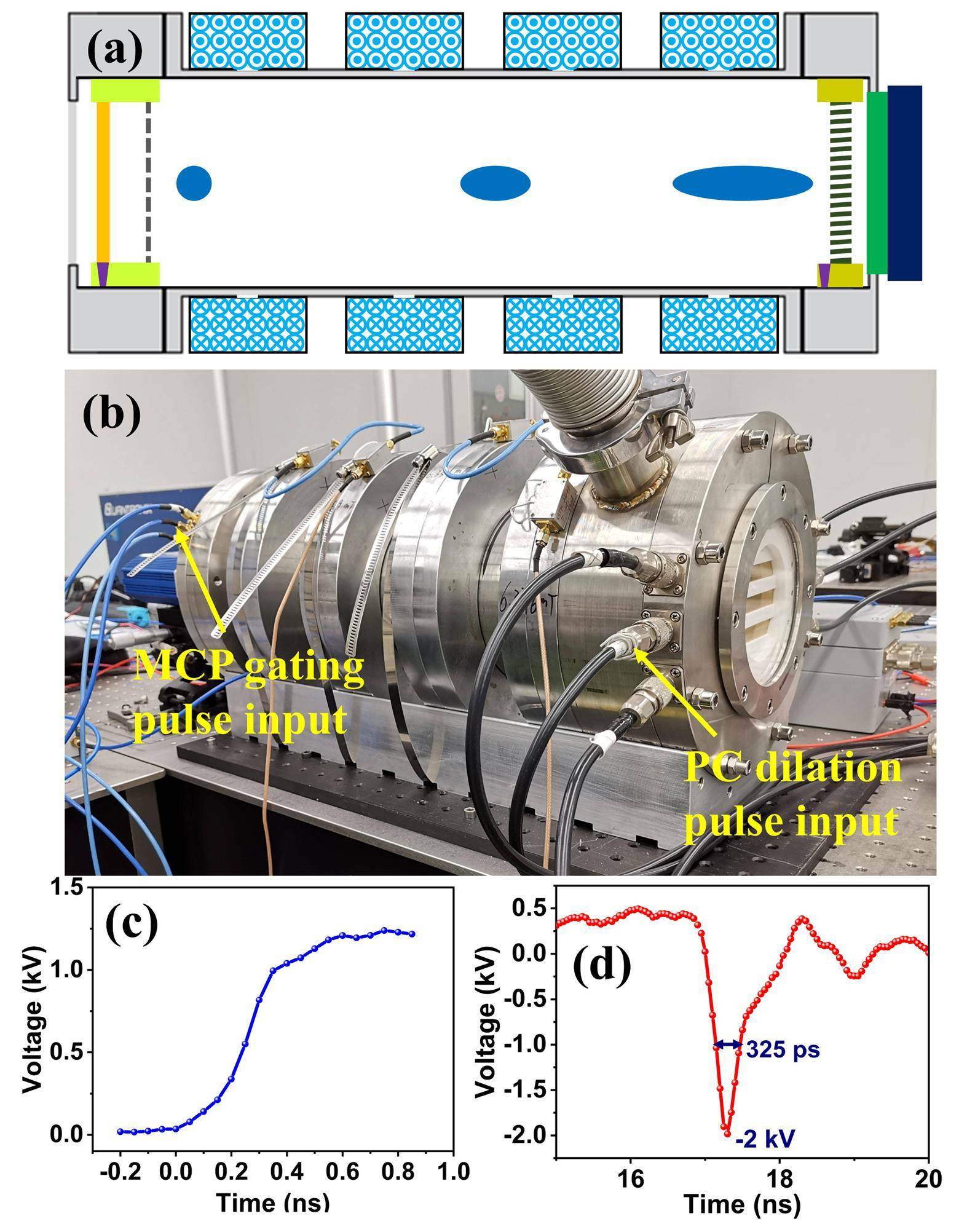
The MCP imager consisted of an MCP, a phosphor screen, and a charge-coupled device (CCD). The thickness, diameter, and pore diameter of the MCP were 0.5 mm, 106 mm, and 12 μm, respectively. The three microstrip transmission lines were formed by depositing 500 nm Cu overlaid with 100 nm Au on the MCP input surface. The entire MCP output surface was also deposited with Cu and Au with the same thicknesses and connected to the ground. A width of 12 mm for each microstrip transmission line and a 10 mm gap between two adjacent lines were formed. The phosphor screen was biased with a +3.4 kV DC voltage and positioned 0.5 mm from the MCP. The CCD was a fiber coupled with the phosphor screen to capture visible light images.
The drift region for electron pulse dilation, from the mesh to the MCP, was 550 mm. The electrons travelling in the drift tube were imaged from the PC to the MCP by an axially symmetric nonuniform magnetic field produced by the combined magnetic lenses [28, 33]. Four identical annular magnetic lenses were used to form the combined-lens imaging system. The magnetic lens was composed of a soft iron frame and 2320-turn copper coils whose outer diameter, inner diameter, and axial length were 256 mm, 160 mm, and 50 mm, respectively. In the inner cylinder, a 4 mm circular slit was formed to release the magnetic field from the soft iron to the drift tube.
The output of the pulse generator consisted of three PC dilation pulses and three MCP gating pulses. The pulse generator comprised a transistor ramp pulser and pulse-width-shortening diode circuit. In the transistor ramp pulser, eight avalanche transistors were stacked in a string, and seven strings were configured in a Marx-bank circuit. The transistor ramp pulser produced six ramp pulses, three of which were used for PC dilation pulses to drive the three PCs, while the other three were used to separately drive the diode circuit to produce three MCP gating pulses [28]. Each PC dilation pulse had an effective rising time of approximately 400 ps, as shown in Fig. 1(c), and its slope was approximately 2.5 V/ps. Furthermore, the MCP gating pulse was obtained with an amplitude and a width of −2 kV and 325 ps, respectively. The corresponding waveform is shown in Fig. 1(d).
Performance measurement results
Spatial resolution measurement
The spatial and temporal resolutions of the cameras were measured. A tailored Au PC was used instead of an X-ray PC to measure the spatial resolution at different off-axis distances. The Au PCs were fabricated by depositing an 80 nm Au film on a quartz substrate. Photolithography was used to develop a resolution mask for each PC [34]. The resolution mask comprised several slits with dimensions of 3 mm × 3 mm. The slits had various spatial frequencies, namely 500, 200, 100, 66, 50, 40, 33 and 28 μm. Two slits, whose directions were parallel and perpendicular to the PC transmission line, were used for each spatial frequency. Eight spatial frequencies with sixteen slits are formed to a slit group. Several slit groups were deposited repetitively along each PC to measure the spatial resolution at different off-axis distances.
The spatial resolution of the camera, which is determined by the combined magnetic lenses and MCP imager, can be expressed as [19, 22]:
Here, δdrift is the spatial resolution of the combined magnetic lenses; δMCP = 50 μm is the spatial resolution of the MCP imager; and the spatial magnification ratio Ms is 1. As δMCP and Ms are fixed, δ is primarily influenced by the combined magnetic lenses.
The spatial resolution was simulated as follows. Lorentz3DEM software was used to simulate the electromagnetic field from the PC to the MCP of the camera, and the resulting electron trajectories were traced. The spatial resolution of each off-axis position was obtained using the Rayleigh criterion. Two photoelectron beams were emitted at specific positions on the PC, and their corresponding image points on the MCP were obtained. The minimum distinguishable distance between the two image points was obtained using the Rayleigh criterion, and the corresponding gap between the two photoelectron beams on the PC was determined as the spatial resolution.
The static spatial resolution measurements were performed using a DC ultraviolet source. A static DC voltage was applied to both the PC and MCP. The PC converted the incident ultraviolet light to a photoelectron image with a mask. The photoelectron image was then imaged onto the MCP by combined magnetic lenses and converted to a visible image by the MCP imager. Finally, a CCD was used to capture the visible images.
The spatial resolution characteristics of the cameras with different numbers of magnetic lenses were compared. The number of magnetic lenses was increased, and the static image of the corresponding camera was obtained. When the camera consists of one magnetic lens, the static image on the Gaussian plane of the middle transmission PC is shown in Fig. 2(a). Static images with resolution masks when the camera comprises two, three, and four magnetic lenses are shown in Figs. 2(b), (c), and (d), respectively. The spatial resolution is obtained from the static image, and the modulations of the slits for different spatial frequencies are given by
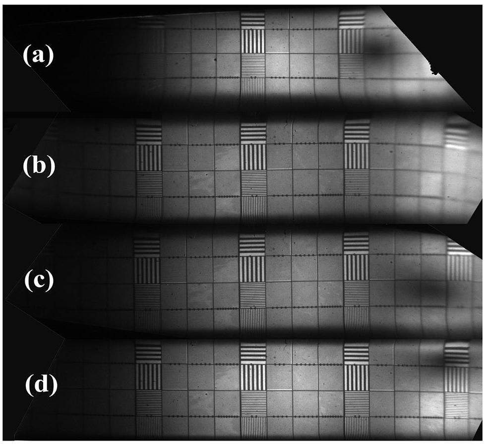
Here, I, Imax, and Imin denote the corresponding intensity of the slit image, maximum intensity, and minimum intensity, respectively. The measured and simulated results were compared.
The 200 μm mask for various off-axis distances and magnetic lens numbers are shown in Fig. 3(a), and their corresponding modulations are shown in Fig. 3(b). The lines and points represent the simulated and measured results, respectively. The camera with one magnetic lens exhibits the worst imaging quality. The modulation decreases rapidly with increasing off-axis distances. It cannot distinguish 200 μm when the off-axis distance exceeds 13.5 mm. The camera with two, three, or four magnetic lenses exhibits considerably better imaging quality than the single magnetic lens camera. The camera that uses four magnetic lenses exhibits better spatial resolution than that using two or three lenses. In the camera with four magnetic lenses, the entire effective working area with diameter of 60 mm delivers a spatial resolution better than 200 μm. The measurement and simulation results are consistent, and show that the modulation worsens with increasing off-axis distance. Therefore, the spatial resolution decreases with increasing off-axis distance.
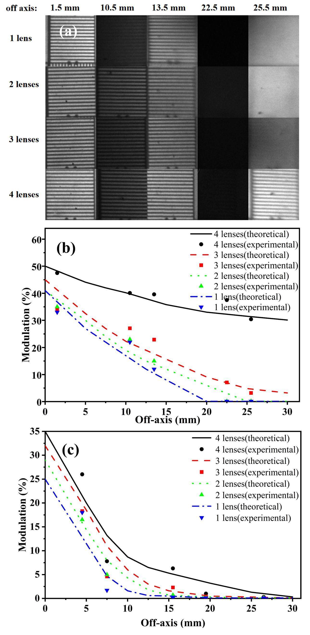
The modulations of the 100 μm masks on the Gaussian plane versus off-axis distances are shown in Fig. 3(c). The visibility of the 100 μm mask reduces when the off-axis distance increases. The 100 μm mask can be distinguished within the area with radius of 4.5 mm when one magnetic lens is used. The imaging quality significantly improves when the camera uses four magnetic lenses. However, the 100 μm mask in the PC off-axis 26.5 mm does not exhibit visible modulation. The camera cannot have a working area with a radius of 26.5 mm for 100 μm spatial resolution on the Gaussian plane. Furthermore, the modulation for the 100-μm mask descends faster than that for the 200- μm mask along the off-axis distance.
The off-axis spatial resolution is primarily influenced by the field curvature, which is a type of aberration that transforms an imaging plane into a curved surface. The curvature close to the axis is approximately spherical. In the magnet–lens imaging system, the curvature radius rp of the image surface is given by [35]
Here, e and m are the electron charge and mass, respectively; V is the voltage between the PC and the mesh; B is the magnetic field strength in the drift tube; and z is the axial direction variable.
The field curvature is a complex parameter because the curvature radius rp varies with the off-axis distance. The imaging surface was simulated using the Lorentz3DEM software. The curved imaging surfaces for cameras consisting of various numbers of lenses and their two-dimensional projections are shown in Fig. 4(a) and Fig. 4(b), respectively. The lines represent the simulation results for a PC with a simulation area diameter of 60 mm. The parameter L is the distance from the imaging surface to the PC along the axis, which represents the position of the imaging surface for each off-axis point. The simulation results show that the imaging surface is curved when the PC voltage is fixed. Although the object point has a larger off-axis distance, its corresponding L is smaller, which indicates that the imaging point is located closer to the PC for a farther off-axis object point.
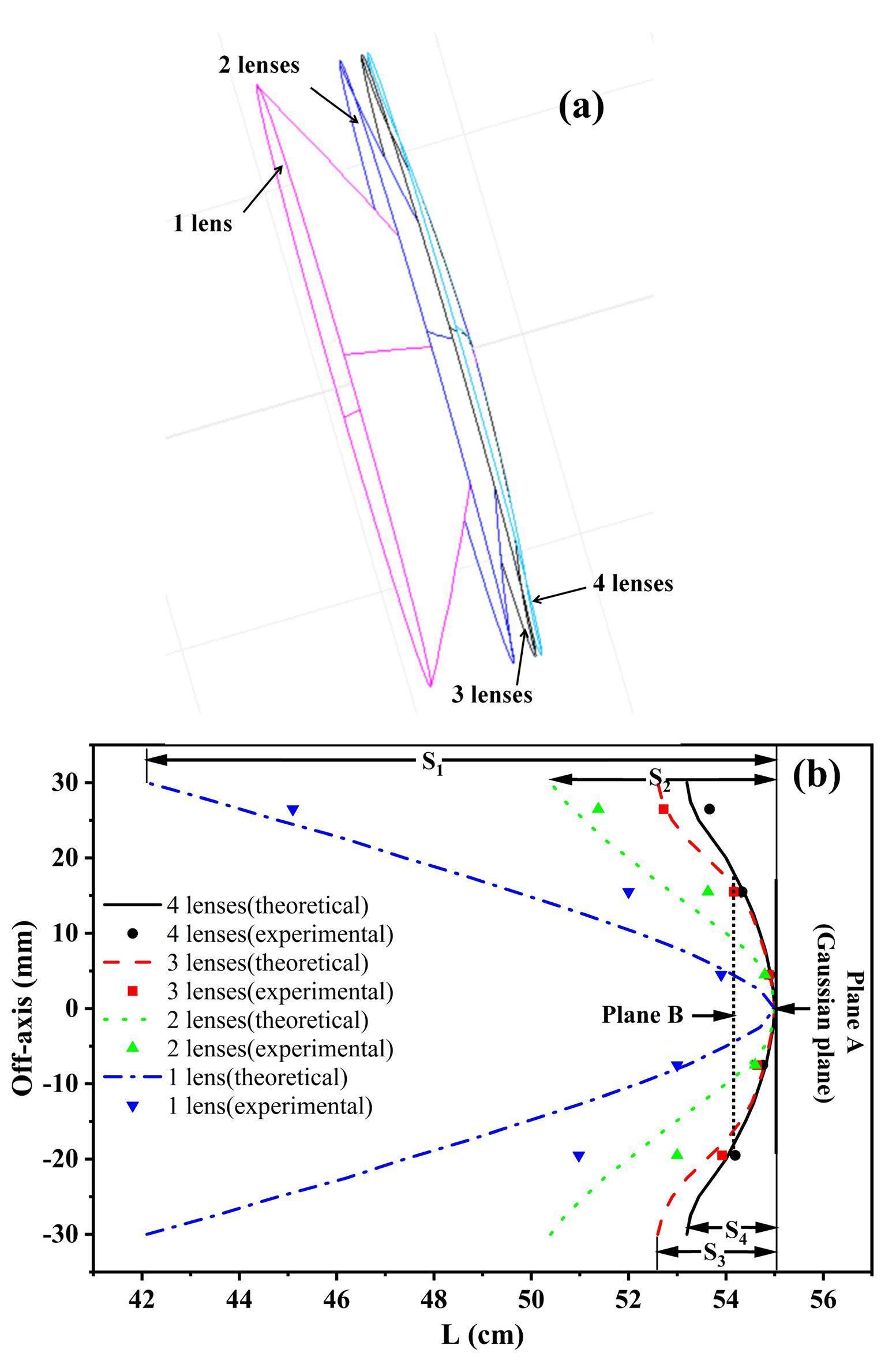
In the experiment, the imaging surface was detected using a planar MCP, and the distance between the PC and MCP was fixed in the camera. Therefore, the position of the imaging point for each off-axis object point could not be simultaneously obtained in an experiment with the same PC voltage. The imaging-point positions were obtained from different experiments using different PC voltages. The PC voltage was adjusted in turn, resulting in a sequence of the clearest areas of the image on the MCP. Subsequently, the PC voltage for each object point on the PC that was imaged clearly on the MCP was obtained. In the camera with four magnetic lenses, the experimental results demonstrated that the distance between the object plane and image surface reduced by approximately 0.14 mm when the PC voltage increased by 1 V. Similar results were obtained for the other magnetic lens imaging systems. Therefore, the variation in PC voltage can be used to obtain the imaging point position of each PC object and its corresponding variation [35]. The experimental results of the position of the imaging point versus the off-axis distance of the PC object point are shown in Fig. 4(b). In Fig. 4, the lines and points represent the simulation and experimental results, respectively. The experimental results are consistent with the simulation results. The position of the imaging point is moved to the PC when the off-axis distance of the object point is increased, leading to a curved imaging surface. However, the detector of the curved imaging surface is a planar MCP; consequently, the spatial resolution varies with the off-axis distance of the electrons emitted from the PC. Therefore, the uniformity of the spatial resolution over the entire sensitive area of the PC was reduced.
In Fig. 4(b), plane A is the Gaussian plane, and the curved imaging surfaces are the Petzval surfaces [35]. S1, S2, S3, and S4 are the axial deviations between the Gaussian plane and Petzval surface with an aperture radius of 30 mm. The maximum in the camera with one magnetic lens, S1, is approximately 13 cm. The deviation S2 decreases to 5 cm when two magnetic lenses are used. A better curvature is achieved by using three magnetic lenses, and the deviation S3 is approximately 2.5 cm. The field curvature further improves in the camera with four magnetic lenses, and deviation S4 improves to less than 2 cm. The improvement in the field curvature enhances the spatial resolution with an increasing number of magnetic lenses, which explains the experimental results shown in Fig. 3.
The location of the Gaussian plane A for the camera imaging system was adjusted to improve the uniformity of the spatial resolution in the entire sensitive area of the PC. The PC voltage of −3 kV was fixed, while the magnetic lens excitation currents were reduced. The Gaussian plane A was moved farther from the PC. The spatial resolution differences in the working area improved when the plane B in Fig. 4(b) was moved to overlap with the MCP plane. Fig. 5(a) shows the 200 μm static images of the slits on the imaging plane B, while Fig. 5(b) shows its modulations varying with off-axis distance. Compared to the results for the Gaussian plane A in Fig. 3(a), the off-axis spatial resolution of off-axis 25.5 mm is significantly improved. The 200-μm mask on the radius of 25.5 mm was distinguishable in the camera with four and three magnetic lenses. Fig. 5(b) shows that changing the imaging plane from A to B improves the modulation for the off-axis region. However, the modulation of the on-axis area decreases. Fortunately, the spatial resolution differences over the entire working area improve. Comparing the modulation difference of plane B in Fig. 5(b) with that of plane A in Fig. 3(b), the modulation difference among the points within a 30 mm off-axis distance in plane B is better than that in plane A. Therefore, the uniformity of the spatial resolution of the entire working area for plane B is better than that for plane A.
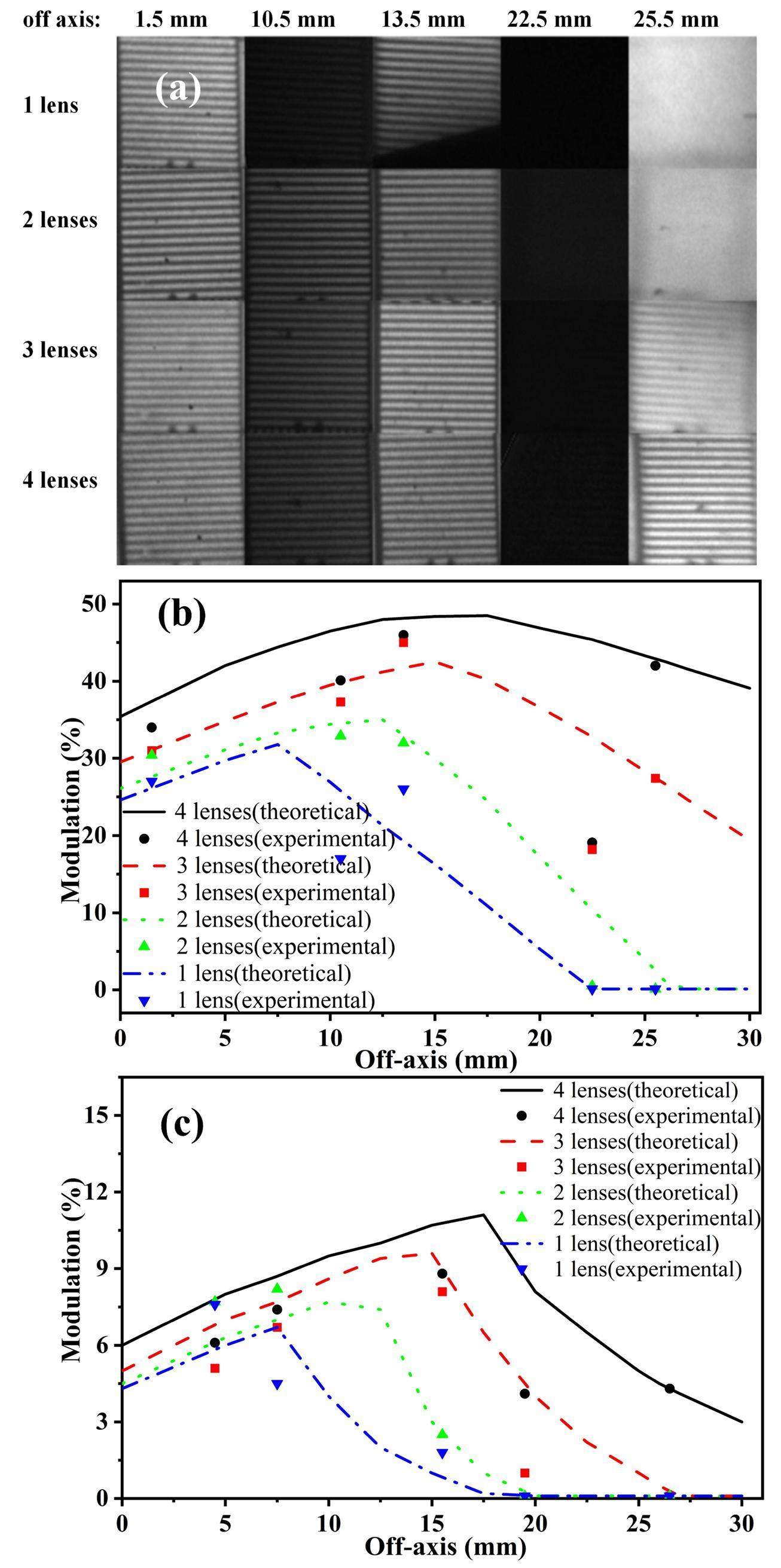
The modulations of the 100 μm slits for the static images on the imaging plane B are shown in Fig. 5(c). The 100 μm spatial resolution with radius of 26.5 mm is distinguishable in the camera with four magnetic lenses. Further, multiple combined magnetic lenses produce better imaging quality than a single magnetic lens. The camera with four combined magnetic lenses achieved a spatial resolution of 100 μm in a sensitive area with a diameter of 53 mm.
Temporal resolution measurement
The energy spread at the mesh results in temporal magnification of the electron pulse in the drift tube, which greatly improves the temporal resolution. The temporal resolution T of the pulse-dilation framing camera is mainly determined by the temporal resolution TMCP of the MCP imager and the pulse-dilation temporal magnification factor M, which is given by [21]
The pulse dilation temporal magnification factor M is determined by the PC voltage, PC dilation pulse slope, and drift tube length [26]. Because of the small distance from the PC to the mesh and the negligible initial electron energy spread at the PC, the electrons that enter the drift tube at time ti reach the MCP at time
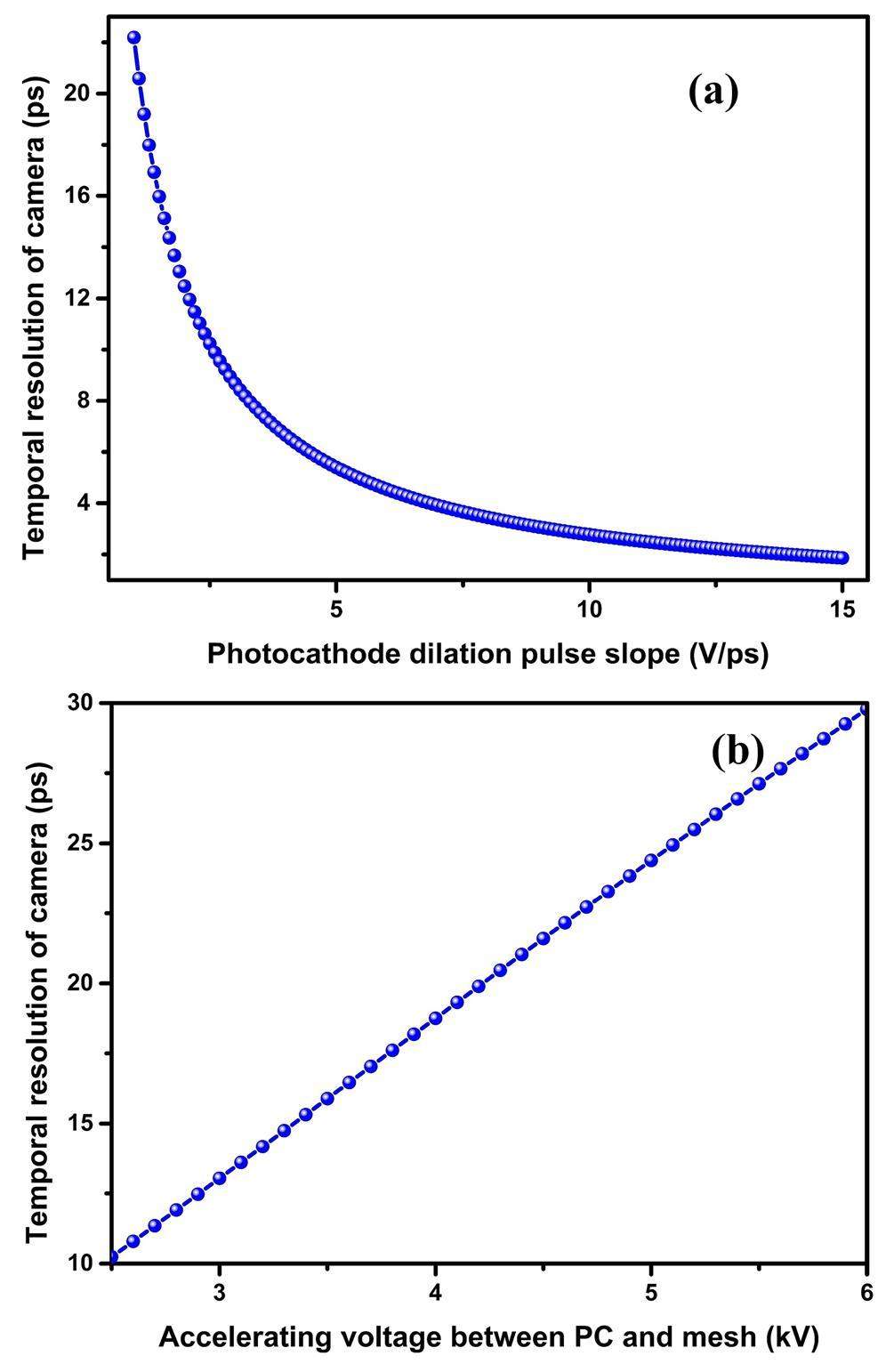
In general, the drift tube length is determined when the pulse-dilation framing tube is designed. The temporal resolution T is primarily determined by the PC voltage, PC dilation pulse slope, and MCP imager resolution [26]. As shown in Fig. 6, the variation of the temporal resolution T of the camera with the PC dilation pulse slope and its relationship with the PC voltage were studied when the temporal resolution of the MCP imager was 100 ps. The temporal resolution improves with increasing PC dilation pulse slope. This is because the temporal magnification factor M increases with the PC dilation pulse slope. In Fig. 6(a), a voltage of −2.5 kV is applied to the PC. As shown in Fig. 6(b), the PC dilation pulse slope is 2.5 V/ps. Figure 6(b) shows that the temporal resolution improves with decreasing the accelerating voltage. The accelerating voltage is an important parameter for the camera because both the electron transit time spread from the PC to the anode mesh and the spatial resolution improve with increasing acceleration voltage [31, 32]. The acceleration voltages of the pulse-dilation framing cameras are typically higher than 2.5 kV [21, 36].
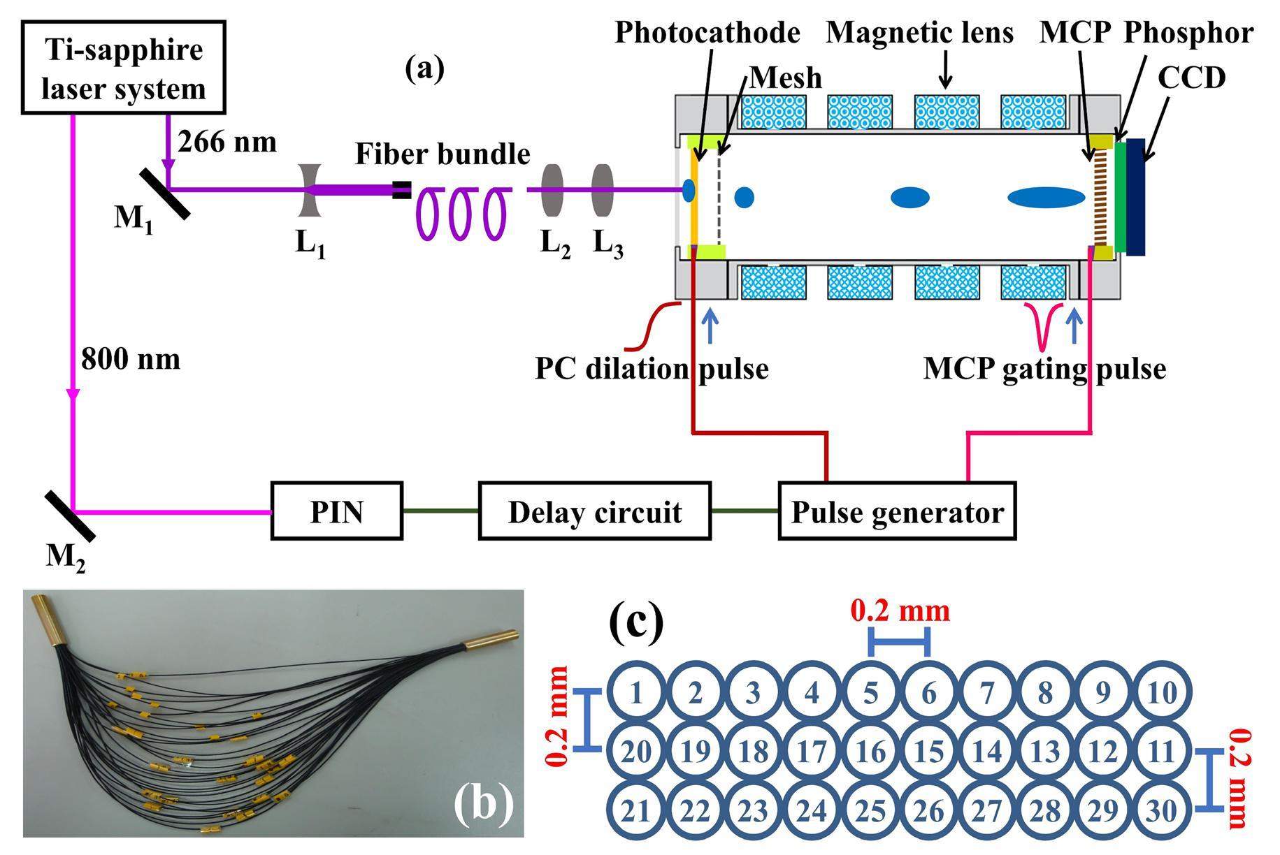
The temporal resolution was measured using a femtosecond laser and fiber bundle. The measurement setup included a Ti-sapphire femtosecond laser system, an optical time adjustment system, a fiber bundle, an optical imaging system, an electric trigger signal generator, an electric delay circuit, and the pulse-dilation framing camera, as shown in Fig. 7(a). Two laser beams with wavelengths of 266 nm and 800 nm were emitted by the femtosecond laser system. The 266 nm UV light was used to excite photoelectrons, while 800 nm infrared light served as a synchronous trigger signal. UV light with a pulse width of 130 fs was reflected by a total reflection mirror M1, and the spot size of the UV light was then enlarged by a concave lens L1. The fiber bundle was composed of 30 fibers and was used to separate the input UV laser into 30 light points. The lengths of the 30 fibers were increased with an equal difference of 2 mm, and the error was less than 0.2 mm. Therefore, 30 UV light points were generated at various times. A delay of approximately 10 ps was achieved for each pair of adjacent light points. Photographs of the fiber bundle and an array diagram of the fiber output port are shown in Fig. 7 (b) and (c), respectively. The 30 UV light points obtained from the fiber bundle are imaged onto the PC using lenses L2 and L3, which generates 30 photoelectron pulses. The emission time interval for each pair of neighboring photoelectron pulses is approximately 10 ps.
First, the static image of 30 laser pulses was acquired, as shown in Fig. 8(a). The PC and MCP were subjected to static DC voltages of −3 kV and −700 V, respectively. The top-right image point is imaged from the shortest fiber, and each pair of neighboring images is 0.5 mm apart. The static image represents the light intensity uniformity of the 30 light points, which is used as a normalized background image for the gating image.
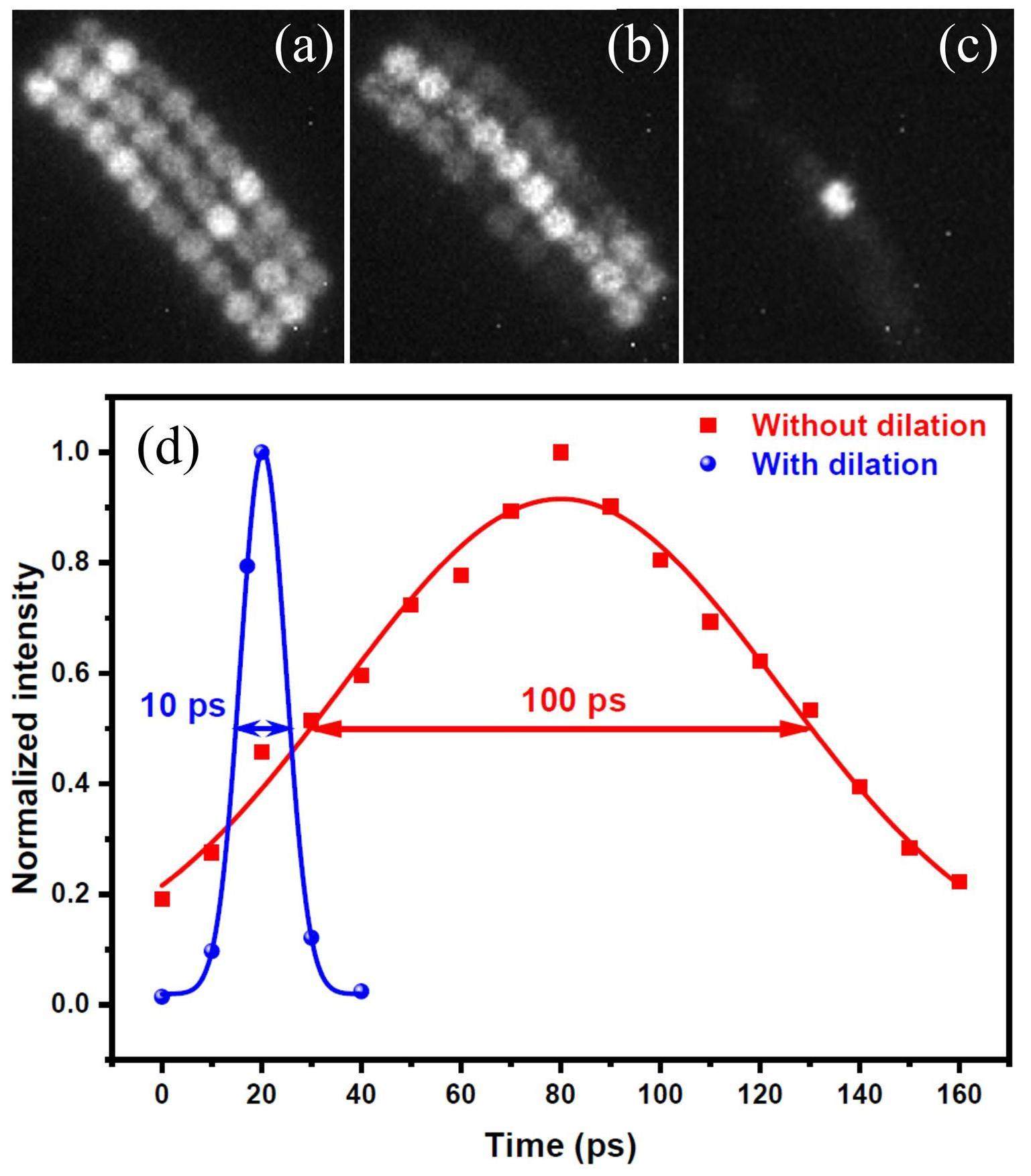
The gated image of the camera without pulse dilation (Fig. 8(b)) was measured by applying a −2.5 kV static DC voltage on the PC and a −483 V DC bias plus the gating pulse as described above for the MCP. When a static DC bias was applied to the PC, the electron beam was not temporally dilated. The MCP was driven by the gating pulse and the electron signal was sampled by the MCP imager. Thus, we measured the gate width of the MCP imager. Figs. 8(a) and (b) show two raw CCD images. To reduce the effect of the nonuniform light intensity distribution, the static results from Fig. 8(a) were used to correct the gating results in Fig. 8(b). A lineout of the corrected data is shown in red in Fig. 8(d). The solid red block points represent the experimental results, which were Gaussian fitted to obtain the intensity versus time curve. The full width at half maximum (FWHM) of the Gaussian curve is defined as the temporal resolution of the camera. Fig. 8(d) shows that, while the electron signal is not dilated, the temporal resolution is approximately 100 ps, which is the temporal-resolution TMCP of the MCP imager.
Finally, the gated image for the camera with pulse dilation was measured, as shown in Fig. 8(c). The MCP was gated, and subjected to a −483 V DC bias and the gating pulse. The PC was excited by a dilation pulse and −3 kV DC bias. Therefore, the photoelectron pulses were temporally dilated and the temporal resolution of the camera improved significantly, as shown in Equation (4). To obtain pulse dilation, all or part of the 30 photoelectron pulses were synchronized with the rising edge of the PC dilation pulse. In this experiment, the arrival time of the laser pulses at the PC was constant, and the timing of the PC dilation pulse was accurately adjusted using a delay circuit to synchronize the PC dilation pulse with the photoelectron pulses. A good synchronization position was achieved in many of the experiments, which was approximately 235 ps relative to the starting time of the PC dilation pulse. The PC voltage at this synchronization position is approximately −2.5 kV. The measured gated image of the camera with pulse dilation when the synchronization position is 235 ps and the photoelectron pulses are dilated is shown in Fig. 8(c). The lineouts of the results from Fig. 8(c) are indicated in blue in Fig. 8(d), which shows that the temporal resolution T of the pulse-dilation framing camera is approximately 10 ps. The temporal magnification factor M was acquired from the PC voltage, temporal resolution TMCP of the MCP imager, and temporal resolution T of the pulse-dilation framing camera. The measured M was 10, which was consistent with the theoretical result of 10.2 calculated using Eq. (6).
X-ray diagnosis applications
A pulse-dilation framing camera was used to detect the X-rays generated by the terawatt laser target device. The experimental setup for the X-ray pulse measurement was similar to the temporal-resolution measurement setup shown in Fig. 7(a). However, the fiber bundle was not used for the X-ray measurements. Two laser pulses with wavelengths of 390 nm and 780 nm and pulse widths of 100 fs were emitted from the terawatt laser system. The laser with a wavelength of 780 nm had an energy of 650 mJ. It was first reflected by several total reflection mirrors and then irradiated onto a planar iron target to produce X-rays. The camera was placed outside the target chamber, and a distance of 71 cm was measured between the PC and iron target. Because no component was placed between the PC and the iron target, the X-rays freely reached the PC to produce photoelectrons. The laser with a wavelength of 390 nm was reflected from another total reflector to a positive-intrinsic-negative (PIN) diode, which produced a trigger signal for the pulse generator. The framing camera was operated in the pulse-dilation dynamic mode. A DG535 delay generator was used to precisely adjust the trigger time to synchronize the X-rays with the PC dilation pulse. Subsequently, the gated images with pulse dilation were obtained.
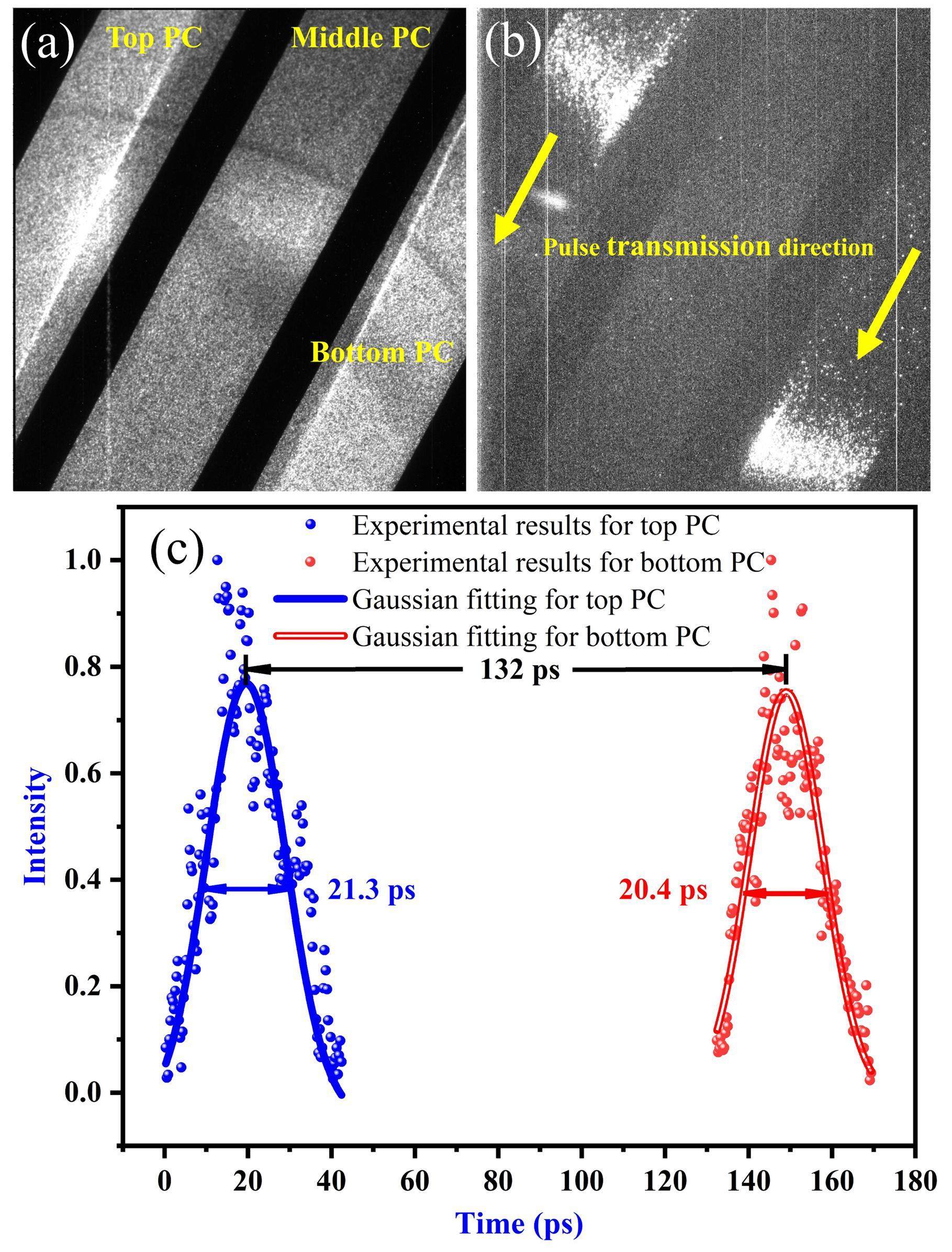
In this experiment, a middle-transmission PC was used as a monitor, and a DC voltage or dilation pulse was not applied. Firstly, the static image of the transmission PC was measured, while the PC was subjected to a −3 kV static DC voltage and the MCP is biased with −700 V. A measured image is shown in Fig. 9(a). A nonuniform intensity distribution is observed in Fig. 9(a) because of the nonuniform spatial distribution of the X-rays. Then, the gating image of the transmission PC for the camera with pulse-dilation is acquired (Fig. 9(b)) when both the top and bottom PCs are subjected to a dilation pulse in addition to the −3 kV DC bias and the MCP is subjected to a −483 V DC bias in addition to the gating pulse. Two coaxial cables of different lengths were used to achieve two dilation pulses reaching the top and bottom PCs at different times, which acquired X-rays at various times for the two PCs. The dilation pulses on the two PCs were synchronized with the X-ray pulses. Thus, two gated images were obtained. The intensity distribution along the MCP was obtained from Fig. 9(b). Because of the 1:1 magnification ratio, the PC area related to the gated image is the same as that in the MCP. The dilation pulse was transmitted across the PC from left to right at a velocity of approximately 1.87 × 10⁸ m/s, which was measured by the time-domain reflection method [36, 37]. Subsequently, the intensity with varying transmission times along the PC for the gating image was obtained from the gating image spatial distribution and PC dilation pulse velocity, as shown in Fig. 9(c). The final results shown in Fig. 9(c) were calibrated using the static results shown in Fig. 9(a). Fig. 9(c) shows the intensity versus temporal distribution of the X-ray pulse. The solid points and lines represent the experimental results and Gaussian fitting curves, respectively. The blue and red regions show the results for the top and bottom PC, respectively. The FWHMs of the Gaussian-fitting curves are 21.3 ps and 20.4 ps. The two FWHMs are almost identical, and their difference is within 5%. Each Gaussian fitting curve is the convolution result of the camera intensity versus time curve with the X-ray intensity versus temporal distribution. Considering that the FWHM of the camera intensity versus time curve was 10 ps, the FWHM of the temporal distribution of the X-rays was approximately 18 ps from the deconvolution result. This indicated that the X-ray pulse had a width of approximately 18 ps. Furthermore, Fig. 9(c) shows that the delay time between the dilation pulses for the top and bottom PCs is approximately 132 ps.
Conclusion
An ultrafast pulse-dilation framing camera combined with magnetic lenses was developed. The camera used a pulsed PC to achieve high temporal resolution and four magnetic lenses to improve the spatial resolution. A temporal resolution of 10 ps and spatial resolution of 100 μm were obtained. The spatial resolution characteristics of the camera were also studied. Different numbers of magnetic lenses were applied to the camera to compare the spatial resolution. Both the theoretical and experimental results showed that the spatial resolution of the camera using a single magnetic lens was the worst; however, the spatial resolution improved when the camera used combined magnetic lenses. The camera with four magnetic lenses exhibited better spatial resolution than the other cameras. Furthermore, the field curvatures of the cameras with different numbers of lenses were measured. The results also showed that the four-magnetic lens camera had a lower field curvature than the other cameras, resulting in better spatial resolution and larger working area. Moreover, the axial location of the imaging plane influenced the spatial resolution uniformity of the on- and off-axis areas, which limited the working area. An appropriate imaging plane was obtained for the camera with four magnetic lenses, and a working area with a diameter of 53 mm was achieved. The camera was used to detect X-rays, and the diagnostic results indicated that the width of the X-ray pulse was approximately 18 ps.
Fuel gain exceeding unity in an inertially confined fusion implosion
. Nature 506, 343-348 (2014). https://doi.org/10.1038/nature13008Study of achromatic beamline design for laser-driven femtosecond electron beams
. Nucl. Tech. 46, 020201 (2023) https://doi.org/10.11889/j.0253-3219.2023.hjs.46.020201. (in Chinese).Two-dimensional time-resolved ultra-high speed imaging of K-alpha emission from short-pulse-laser interactions to observe electron recirculation
. Appl. Phys. Lett. 110, 144102 (2017). https://doi.org/10.1063/1.4979802Primary yields of protons measured using CR-39 in laser-induced deuteron-deuteron fusion reactions
. Nucl. Sci. Tech. 31, 62 (2020). https://doi.org/10.1007/s41365-020-00769-8Design of the neutron slit package for Femi chopper prototype of CSNS
. Nucl. Tech. 44, 050201 (2021). https://doi.org/10.11889/j.0253-3219.2021.hjs.44.050201. (in Chinese).Design of a control system with high stability for a streak camera using isolated ADC
. Nucl. Sci. Tech. 29, 22 (2018). https://doi.org/10.1007/s41365-018-0361-9Development of a wide-range and fast-response digitizing pulse signal acquisition and processing system for neutron flux monitoring on EAST
. Nucl. Sci. Tech. 33, 35 (2022). https://doi.org/10.1007/s41365-022-01016-yDevelopment of gated fiber detectors for laser-induced strong electromagnetic pulse environments
. Nucl. Sci. Tech. 32, 58 (2021). https://doi.org/10.1007/s41365-021-00898-8High-speed gated X-ray imaging for ICF target experiments
. Rev. Sci. Instrum. 63, 4813-4817 (1992). https://doi.org/10.1063/1.1143571Application of a fast electrical pulse in gated multichannel plate camera
. Rev. Sci. Instrum. 78, 055104 (2007). https://doi.org/10.1063/1.2737750Development and characterization of a pair of 30–40 ps X-ray framing cameras
. Rev. Sci. Instrum. 66, 716-718 (1995). https://doi.org/10.1063/1.1146268Gain depletion of X-ray framing camera
. Rev. Sci. Instrum. 88, 083514 (2017). https://doi.org/10.1063/1.4999757High speed proximity focused X-ray cameras
. Laser Part. Beams 9, 49-69 (1991). https://doi.org/10.1017/S0263034600002330Measurements with a 35 psec gate time microchannel plate camera
. Proc. SPIE 1346, 456-464 (1991). https://doi.org/10.1117/12.23371Electrostatic-lenses position sensitive TOF MCP detector for beam diagnostics and new scheme for mass measurements at HIAF
. Nucl. Sci. Tech. 30, 152 (2019). https://doi.org/10.1007/s41365-019-0676-1Design of the high-yield time-gated x-ray hot-spot imager for OMEGA
. Rev. Sci. Instrum. 93, 113521 (2022). https://doi.org/10.1063/5.0101673An accumulative X-ray streak camera with sub-600-fs temporal resolution and 50-fs timing jitter
. Appl. Phys. Lett. 82, 3553-3555 (2003). https://doi.org/10.1063/1.1577213Progress of indirect drive inertial confinement fusion in the United States
. Nucl. Fusion 59, 112018 (2019). https://doi.org/10.1088/1741-4326/ab1ecfSub-nanosecond single line-of-sight (SLOS) X-ray imagers
. Rev. Sci. Instrum. 89, 10G123 (2018). https://doi.org/10.1063/1.5039648Development of an ultrafast detector and demonstration of its oscillographic application
. Nucl. Sci. Tech. 33, 72 (2022). https://doi.org/10.1007/s41365-022-01055-5Pulse-dilation enhanced gated optical imager with 5 ps resolution
. Rev. Sci. Instrum. 81, 10E317 (2010). https://doi.org/10.1063/1.3479111Investigating high speed phenomena in laser plasma interactions using dilation X-ray imager
. Rev. Sci. Instrum. 85, 11E504 (2014). https://doi.org/10.1063/1.4890396Electron pulse-dilation diagnostic instruments
. Rev. Sci. Instrum. 94, 021102 (2023). https://doi.org/10.1063/5.0128802Dilation X-ray imager a new/faster gated x-ray imager for the NIF
. Rev. Sci. Instrum. 83, 10E116 (2012). https://doi.org/10.1063/1.4732849Simulation of a dilation X-ray framing camera
. J. Electron. Imaging 26, 043003 (2017). https://doi.org/10.1117/1.JEI.26.4.043003The dilation aided single–line–of–sight x–ray camera for the National Ignition Facility: Characterization and fielding
. Rev. Sci. Instrum. 89, 10G125 (2018). https://doi.org/10.1063/1.5038671Characterization of the hardened single line of sight camera at the National Ignition Facility
. Rev. Sci. Instrum. 93, 083516 (2022). https://doi.org/10.1063/5.0100981Dilation framing camera with 4 ps resolution
. APL Photonics 1, 016101 (2016). https://doi.org/10.1063/1.4945350A grazing incidence x-ray streak camera for ultrafast, single-shot measurements
. Appl. Phys. Lett 96, 134102 (2010). https://doi.org/10.1063/1.3371810Properties of the cathode lens combined with a focusing magnetic/immersion-magnetic lens
. Nucl. Instrum. Methods Phys. Res. Sect. A 645, 55-59 (2011). https://doi.org/10.1016/j.nima.2010.12.232Demonstration of a sub-picosecond x-ray streak camera
. Appl. Phys. Lett. 69, 133-135 (1996). https://doi.org/10.1063/1.118099Achieving 280 fs resolution with a streak camera by reducing the deflection dispersion
. Appl. Phys. Lett. 87, 041103(2005). https://doi.org/10.1063/1.2001732Dilation X-ray framing camera and its temporal resolution uniformity
. Opt. Express 27, 2817-2827 (2019). https://doi.org/10.1364/OE.27.002817Large-format pulse-dilation framing tube with 5 lp/mm spatial resolution
. Optik 185, 441-446 (2019). https://doi.org/10.1016/j.ijleo.2019.03.105Improving the off-axis spatial resolution and dynamic range of the NIF X-ray streak cameras
. Rev. Sci. Instrum. 87, 11E202 (2016). https://doi.org/10.1063/1.4960376Synchronous gating in dilation x-ray detector without 1:1 image ratio
. Opt. Express 27, 12470-12482 (2019). https://doi.org/10.1364/OE.27.012480Gated MCP framing camera with 60 ps exposure time
. Proc. SPIE 2549, 53-59, (1995). https://doi.org/10.1117/12.218320The authors declare that they have no competing interests

