Introduction
Recognized as fourth-generation synchrotron light sources, diffraction-limited storage rings (DLSRs) [1-3] offer high-brightness coherent X-rays. Facilities such as MAX-IV [4], Sirius [5] and ESRF-EBS [6] are currently operating successfully, while the construction of APS-U [7] and HEPS [7] is underway and will benefit from various experimental techniques such as macromolecular crystallography, small-angle scattering, material characterization, new in situ experimental techniques, nanospectroscopy techniques, and other imaging and analysis methods [8, 9].
The Wuhan Advanced Light Source (WALS) [10, 11] was designed as a 1.5 GeV DLSR, with the aim of offering a research frontier platform for many fields. An electron beam with an RMS beam length of 5.5 mm is accelerated in the LINAC stored in the storage ring. The circumference of the ring is 180 m and the designed maximum beam current is 500 mA.
As one of the crucial elements within a synchrotron light source, the radio frequency (RF) system provides supplementary energy to offset synchrotron radiation-induced energy loss. The design of the RF cavity is critical to the overall performance of the storage ring, as it significantly affects important beam parameters including the longitudinal stability and electron beam lifetime [12-15]. In terms of the current trends, DLSRs such as MAX-IV [16] and ESRF-EBS [17] use normal-conducting (NC) continuous-wave (CW) technology [18] instead of superconducting cavities [19-22] as their RF cavities. Employing the NC-CW technology leads to significant cost savings and reduced system complexity.
However, the beam parameters of the WALS storage ring impose stringent requirements on the RF cavity performance. A critical issue that requires attention is the power dissipation of CW cavities. To address this issue, it is necessary to optimize both the RF parameters and thermal distribution. Additionally, the RF cavity in WALS requires stronger higher-order mode (HOM) damping owing to its higher momentum compaction factor (α) and lower synchrotron tuning (Qs).
This study aimed to design and optimize the RF cavity to realize stable RF performance with a lower HOM impedance, which is limited by the WALS threshold. In addition, fabrication and low-power testing of the prototype cavity were completed. In Sect. 2, we discuss the RF performance of the cavity as well as multipacting suppression that may occur in the CW cavity and alternative coupler design. The HOM-damping design and results are presented in Sect. 3. Subsequently, a multiphysics simulation related to the cooling design is discussed in Sect. 4. Finally, prototype machining and low-power tests are presented in Sect. 5.
RF design and optimization
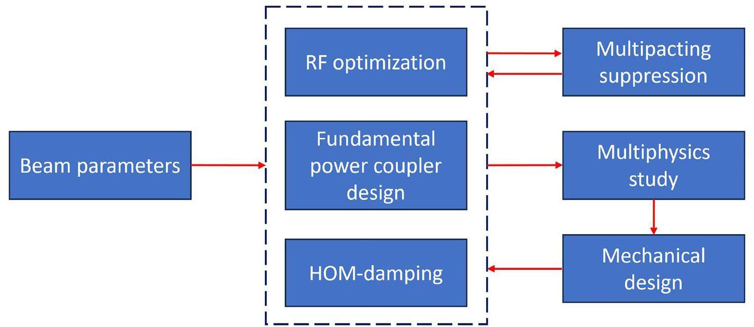
The overall design of the RF cavity is an iterative process that involves RF optimization, multipacting suppression, coupler design, HOM damping, and mechanical design based on multiphysics simulations. As shown in Fig. 1, the functional performance of the cavity was determined using various beam parameters, as listed in Table 1. The RF system operated at a frequency of 499.654 MHz, which is a subharmonic of the S-band LINAC injector [23-25]. WALS has a designed beam current of 0.5 A and momentum compaction factor of 0.00046. These beam parameters impose a relatively strict HOM threshold, and the multicavity scheme further complicates HOM damping. When adopting a single-cell scheme, the required 600 kV accelerating voltage requires optimal RF parameters and thermal distribution design. Therefore, it is important to analyze and optimize the RF cavity accordingly.
| Parameter | Value |
|---|---|
| Beam energy (GeV) | 1.5 |
| Beam current (mA) | 500 |
| Circumference (m) | 180 |
| Energy loss per turn (keV) | 166.5 |
| RF frequency (MHz) | 499.654 |
| Momentum compaction factor,α | 4.6×10⁻⁴ |
| Synchrotron tune, Qs | |
| Damping time, |
13.13,17.80,22.67 |
| RF voltage (kV) | 600 |
| Bunch length (mm) | 5.5 |
The RF design and optimization of the cavity
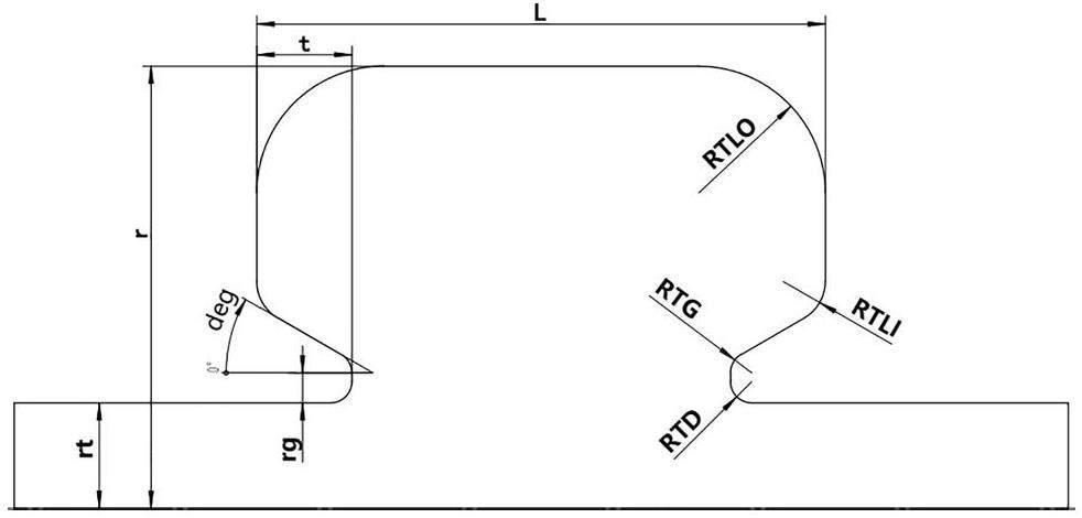
The RF cavity was designed as a reentrant cavity with flat sidewalls that are easy to process (Fig. 2. The RF performance could be adjusted by optimizing the cavity geometry. By studying the cavity, it was found that the geometry of the nose cone plays a significant role in determining the RF performance of the cavity. The gap length affected the transit time, whereas the nose cone angle influenced the peak electric field and power density of the cavity. In addition, the cavity length was closely related to the frequency of the first HOM. Various other factors must be considered when optimizing the cavity design. Given the complexity of this optimization problem, traditional scanning and weighted optimization methods may be inefficient and subjective. Instead, a multi-objective evolutionary algorithm (MOEA) [26] was introduced to enhance the objectivity and optimize the RF performance more effectively.
MOEAs have been extensively employed in accelerator research [27, 28], including beam dynamics in photoinjectors and storage rings [29-32]. In this specific task, multiple geometric parameters must be optimized to achieve a more balanced RF performance, and the single-cell structure eliminates the need for mode identification, making the MOEA an excellent choice for tackling this problem. Each sample must have a unified frequency that matches the design frequency. Optimization utilizes both the non-dominated sorting genetic algorithm II [33] and SUPERFISH [34]. The ideal design minimizes the power dissipation and power density in the cavity while achieving the required 600 kV accelerating voltage.
When applying MOEA to a specific problem, certain constraints should be considered. First, the peak electric field on the cavity surface is expected to remain low to minimize the likelihood of breakdown. Furthermore, the nose cone must penetrate 35-100 mm on one side into the cavity (t), and the radius should not exceed 250 mm owing to manufacturing limitations. The main constraints, optimization parameters, and objectives are presented in Table 2.
| Objective | Limitation | Goal |
|---|---|---|
| Frequency, f (MHz) | 499.654 | Minimize power loss |
| Length, L (mm) | 260-420 | |
| Gap, t (mm) | 35-100 | Minimize peak power density |
| Radius, r (mm) | ≤210 | |
| Voltage (kV) | 600 | Minimize peak E field |
A three-objective optimization was performed several times with 100 populations and 50 generations, starting with a simple re-entrant cavity. During the optimization, the RF performance can converge towards the Pareto front gradually. Figure 3 shows that the power density and power loss are positively correlated and that the surface field strength is mutually exclusive from the other two objectives. Moreover, the results reflect additional RF relations. The cavity length is linearly and negatively correlated with the minimum cavity consumption and minimum peak power density. The length of the nose cone extending into the cavity (t) has a significant influence on local parameters such as the peak power density and peak electric field. The operating point is shown in Fig. 3, which represents the solution of the minimum power density and electric field. The RF performance of the optimized cavity is shown in Table 3.

| Optimized | W/O optimized | |
|---|---|---|
| Frequency (MHz) | 499.654 | 499.654 |
| Voltage (kV) | 600 | |
| R/Q (Ω) | 114 | 96.79 |
| Transit time factor | 0.746 | 0.847 |
| Shunt impedance (MΩ) | 4.37 | 3.34 |
| Power loss (kW) | 41.19 | 53.55 |
| Max power density (W/cm2) | 9 | 16 |
| MaxE (MV/m) | 6.2 | 7.5 |
In the optimized cavity, the peak power density was located near the cavity wall at the nose cone, whereas the peak electric field reached approximately 0.3 kilp. Significant improvements in power loss and power density were observed compared with the unoptimized cavity. The MOEA approach not only improves the efficiency of the optimization, but also increases its objectivity, and the results can reflect some of the phenomena that have been overlooked in the design. In future studies, machine learning or neural network-based optimization techniques can be developed to handle more intricate tasks.
Multipacting suppression of the cavity
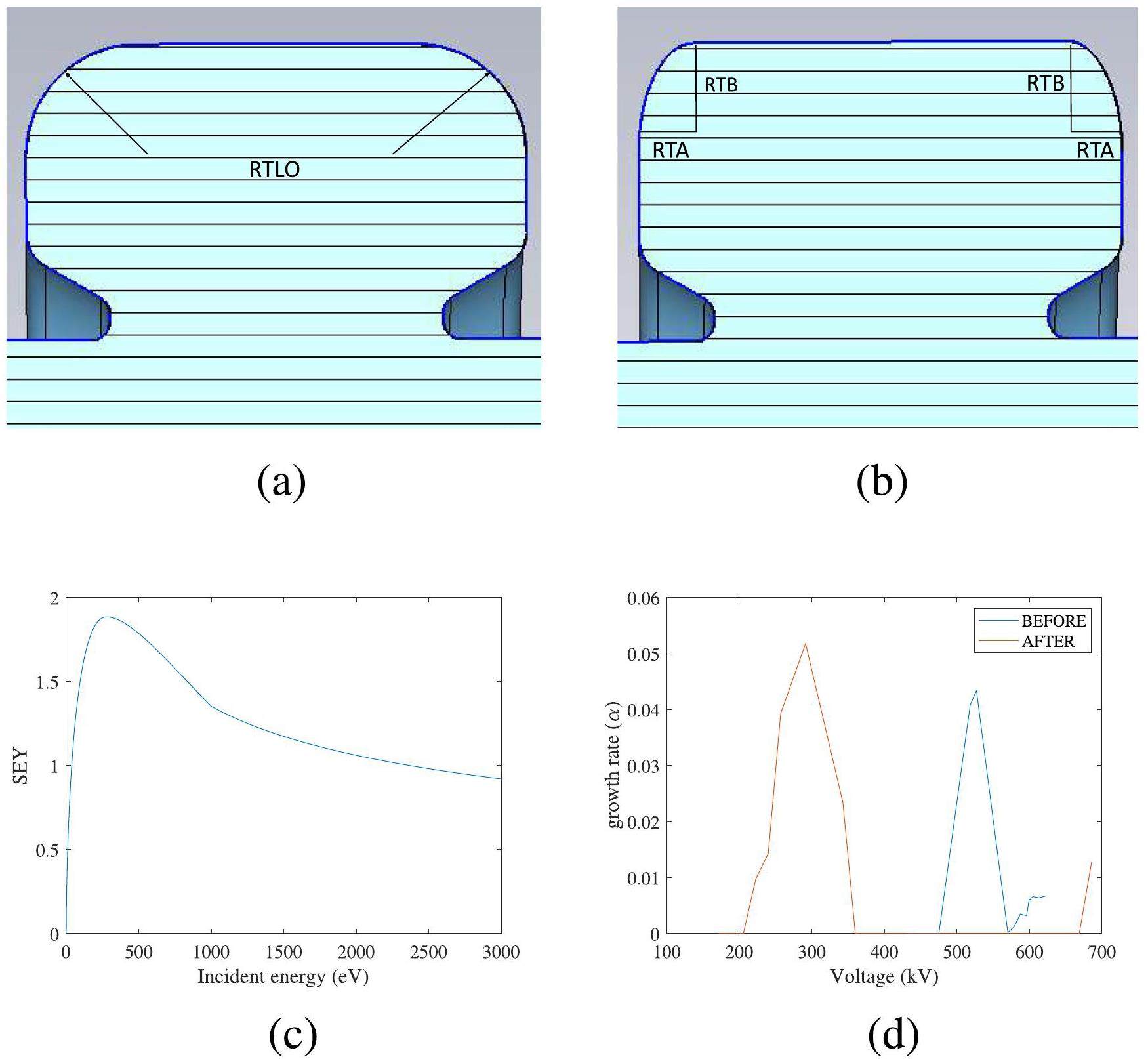
In the CW mode, multipacting is a critical factor that can affect the cavity operation [35]. This results from an oscillatory amplification process of electrons that has the potential to break down the RF cavities and couplers. Multipacting also causes absorption of RF power within the cavity and can damage the inner surface through secondary electron emission. Surface conditions and electromagnetic fields play significant roles in reaching the resonant condition where multipacting occurs [36]. Although the most direct method for suppressing multipacting is surface treatment, geometry optimization of the RF cavity can also be effective [37].
Using CST Particle Studio [38] and the secondary emission yield curve in Fig. 4, multipacting of the cavity wall was observed. When multipacting occurs, the number of particles in the cavity increases exponentially, which can be described by
Coupler design
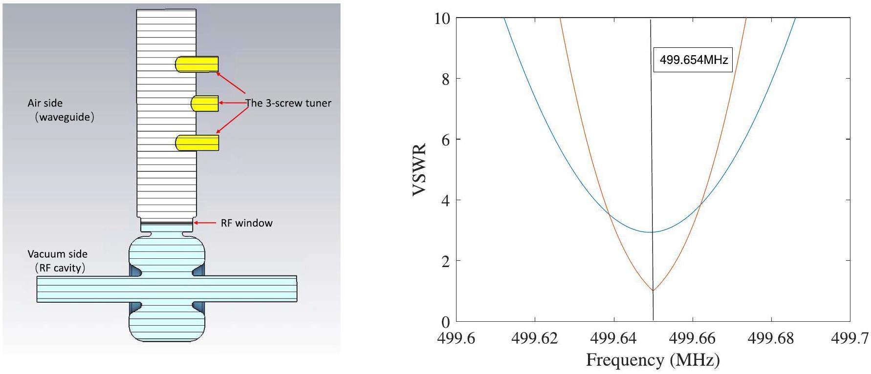
The coupler of an RF cavity is an important component used to transmit RF power. In the 499.654 MHz RF system, the transmitted power is assumed to be 150 kW, and a WR1800 waveguide can be adopted. One of the difficulties in the scheme of direct transmission from the waveguide into the cavity is that the ceramic window used to separate the air and vacuum may complicate the RF system. Considering that designing a vacuum environment in such a large waveguide would cause stress and machining problems, we compressed the waveguide window into a small space near the cavity, as shown in Fig. 5. The ceramic window had a diameter of 200 mm and a thickness of 5 mm and was welded to the flange.
The design requirement for the coupler is that no reflected power exists in the presence of a beam load (
However, in high-power experiments without a beam load, the designed coupling results in wastage of forward RF power. Conventional waveguide-based couplers based on waveguide can hardly allow coupling coefficient adjustment. To achieve continuously adjustable coupling, the ability of a three-screw tuner for VSWR adjustment is introduced. As shown in Fig. 5, the three screws are placed on the air side of the waveguide at a spacing of one-fourth of the waveguide wavelength. Considering that the RF power causes a local temperature rise, the head of the screw is blended elliptically owing to its weaker surface field, smoothed over, and no local high field. As shown in Fig. 5, the coupling coefficient can be verified from one to four.
The possibility of using coaxial couplers for power transfer was preserved in the coupler design. The matching area outside the coupling hole is designed as a cylindrical flange-attachable mechanical structure. When a spare coaxial coupler is required, the RF window can be removed, and the coaxial coupler can be installed directly. Through simulations, the coupling coefficient was continuously adjusted based on the depth and angle of the coaxial coupler.
HOM in the cavity
The HOM caused by a beam passing through an RF cavity is an important factor in the RF design of the cavity. If the frequency of the HOMs overlaps with the beam spectral line and the impedance is higher than the threshold specified by coupled-bunch instabilities [39, 40], beam instability may occur. This threshold can be described by the following equation:
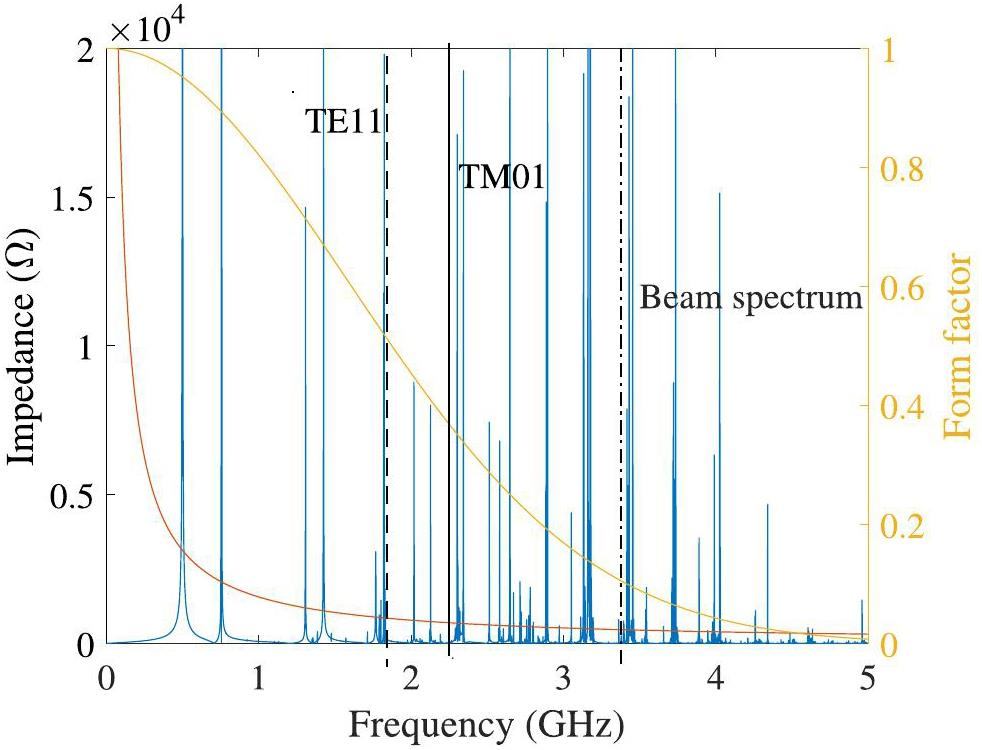
The acceptable HOM impedance depends on the design of the storage ring and beam parameters, as listed in Table 1. Note that the bunch length is considered to increase from 5.5 mm to 30 mm with the introduction of a harmonic cavity [41]. In addition, the effectiveness of the beam frequency spectrum is considered up to the frequency at which the maximum amplitude is reduced to 1/e2 [42], which is approximately 3.5 GHz. However, the modes above the beam tube cutoff frequency can be transmitted through the beam tube. For the current RF design, the cutoff frequencies of the TE and TM modes in the beam tube were 1.795 GHz and 2.295 GHz, respectively.
The impedance of the HOMs was obtained using eigenmode and wake field simulations. Initially, the cavity impedance spectrum was simulated using the wakefield solver with a setup of 5000 m wakelength, which is appoximately 20 times the quality factor. The simulation results are presented in Fig. 6. The impedance of the HOMs was higher than the threshold. These HOMs were then simulated and analyzed using the eigenmode solver. Information such as the Q-factors and R/Q were obtained and are listed in Table 4.
| Mode frequency (MHz) | R/Q (Ω) | Q | R (MΩ) |
|---|---|---|---|
| 754 | 37.79 | 32500 | 0.613 |
| 1305 | 9.14 | 63700 | 0.291 |
| 142 | 20.99 | 35700 | 0.375 |
| 1768 | 5.51 | 41100 | 0.113 |
| 1821 | 5.48 | 58600 | 0.161 |
| 2023 | 3.21 | 89700 | 0.144 |
| 2127 | 1.29 | 60600 | 0.0392 |
By investigating the effectiveness, technical difficulty, and complexity of current HOM damping techniques, a rectangular waveguide with an SiC load [43] was employed in the cavity to perform HOM-damping (Fig. 7, left). The electric and magnetic permeabilities of the SiC loads can be expressed as

The HOM-damping efficiency is related to the width of the HOM waveguide. Owing to space constraints, the cutoff wavelength HOM waveguide was designed to be near the frequency of the first HOM. In addition to adapting to the waveguide width, the distribution of HOM-damping waveguides may lead to different induced efficiencies for each HOM. As shown in Fig. 8, the impedances of the first and third HOMs, denoted as the TM011 and TM021 modes, respectively, increase as the waveguide angle increases. However, the impedance of the mode at 1.8 GHz, which was determined to be a TM022-like mode, and that at 2.1 GHz, which was the TM030 mode, decreased. The optimal damping positions are different for various monopole modes in the cavity. By changing the positions of the HOM waveguides, we can determine an appropriate distribution for the HOM waveguides to achieve a low-HOM impedance distribution.
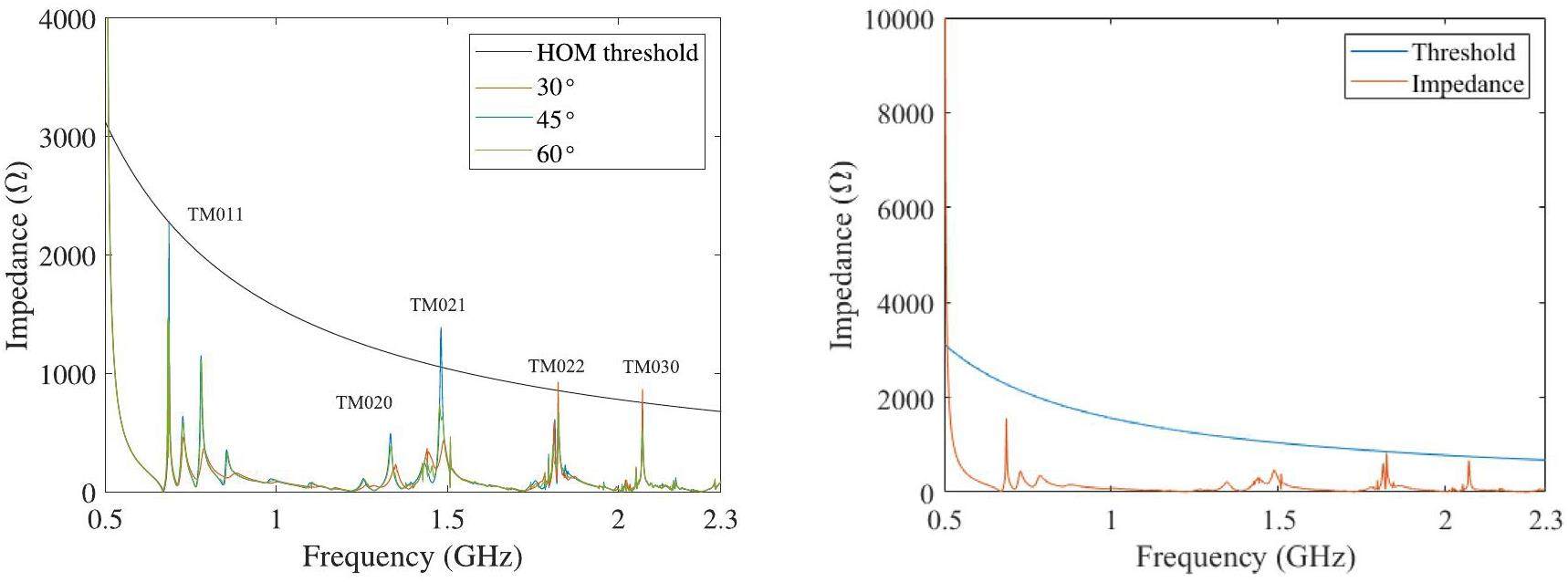
In the latest design, the impedance of all HOMs at frequencies below the cutoff frequency is well below the threshold, as shown in Fig. 8 (right). As presented in Table 5, the coupler and HOM-dampers have no significant effect on the fundamental mode, and the longitudinal impedances of the HOMs within 2.3 GHz are well suppressed.
| Parameters | Valued |
|---|---|
| Frequency (MHz) | 499.654 |
| Voltage (kV) | 600 |
| Quality factor | 31880 |
| R/Q (Ω) | 113 |
| Shunt impedance (MΩ) | 3.7 |
| Power loss (kW) | 50 |
| Accelerating gradient (MV/m) | 1.6 |
Mechanical design and thermal analysis
The RF cavity was operated in the CW mode. Thus, a specific thermal design of the cavity is necessary to reduce the thermal stress and fatigue. For the current RF design, a simulation of cavity heating and cooling was performed.
A drawing of the RF cavity in processing view is shown in Fig. 9. The cavity was formed from three subassemblies: the cavity wall and end caps. The HOM-damping waveguides were located on one end cap, and components such as the coupler, tuner, vacuum pump, and observing port were designed on the cavity wall.
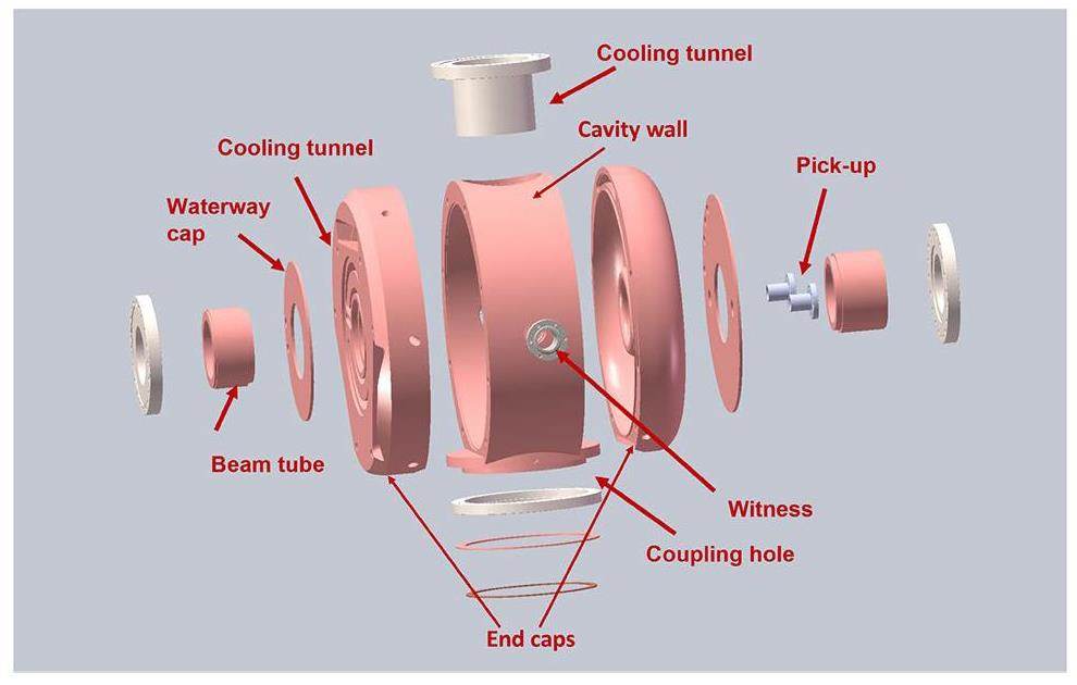
The cavity was mechanically designed using internal water cooling. The heat load on the cavity caused by the RF field is first transferred to the wall of the water circuit by thermal conduction and then removed by the cooling water in the form of thermal convection. The water circuits were distributed according to the RF power density. The peak power density on the cavity surface was located near the nose cone, and was calculated to be 9W/cm2 using SUPERFISH. However, in 3D calculations, additional elements such as couplers and HOM waveguides can introduce changes to the local distribution of the magnetic field. The maximum power densities at the coupling holes were 17W/cm2 and 42W/cm2 in the HOM waveguide. Based on the power distribution and cooling structure, parameters such as the heat coefficients for each region in the simulation are presented in Table 6.
| Location | Left end | Wall | Right end |
|---|---|---|---|
| Channel diameter (mm) | 16 | 16 | 12 |
| Flow rate (m/s) | 1.41 | 1.41 | 1.47 |
| Heat transfer coefficient (W/m2K) | 5970 | 5970 | 6555 |
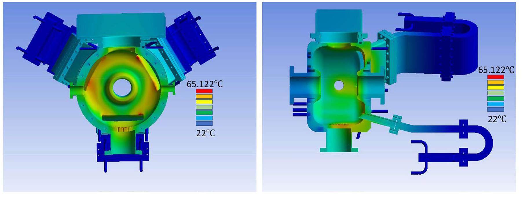
The temperature distribution of the cavity with an input power of 70 kW and an initial temperature of 22 ℃ is shown in Fig. 10. With the current water circuit, the highest temperature increase of 43K occurred at the corner of the HOM waveguide, because the power density at the corner was higher and the cooling area was smaller. The temperature near the nose cone was 46.361 ℃. The simulation indicates that the temperature increase on the cavity wall causes cavity deformation, which eventually shifts the cavity frequency by approximately 282 kHz. The frequency shift can be compensated for by the tuner in the cavity.
Prototype machining and low-power test
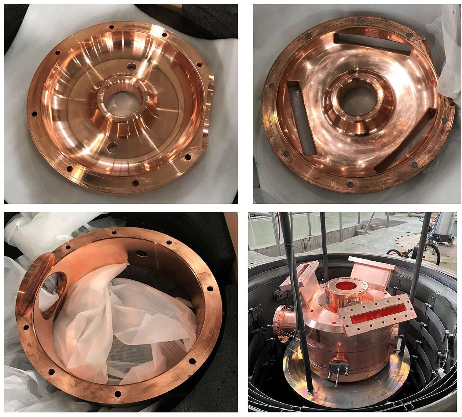
A prototype of the 499.654 MHz RF cavity for processing exploration was manufactured. The machining process was meticulous and precise, and the RF cavity was organized into three distinct parts for machining, as shown in detail in Figs. 9 and 11. The machining process used a vertical lathe to form the machined components. After the two end caps and cavity wall were machined, we assembled the components for the first low-power test; because of the lack of fixturing, the coupling and Q-values were only approximately 1/3 of the design values. Following brazing in a hydrogen environment as shown in Fig. 11, the various RF parameters of the cavity were measured. The coupling coefficient of the RF cavity without the three-screw tuner was 2.62, and the quality factor was 29300, which is close to the designed value.
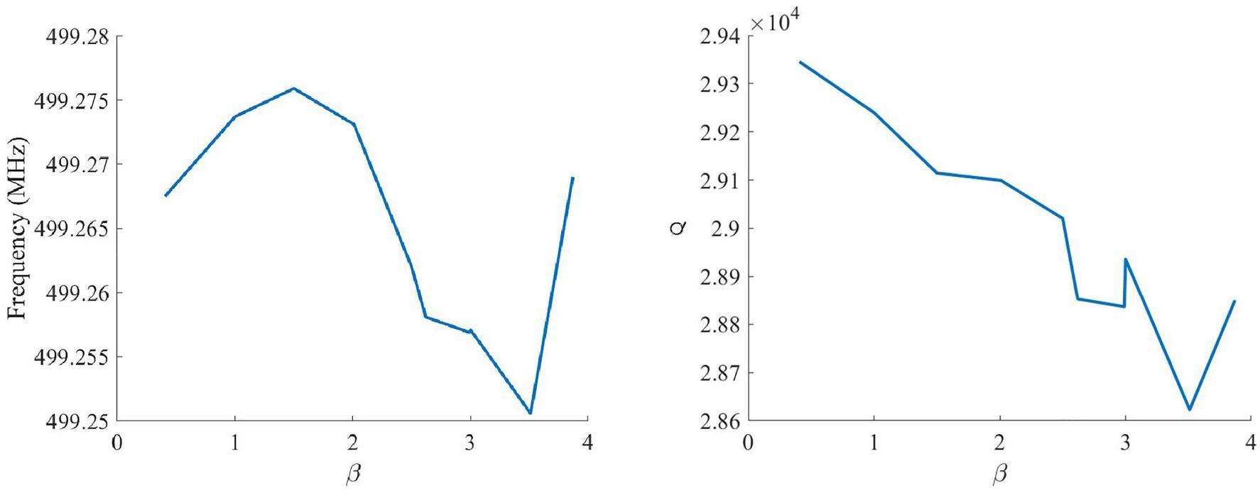
With the three-screw tuner assembled, the coupling coefficient became modifiable. As shown in Fig. 12, the coupling coefficient (β) can be modified between 0.4 to 3.87, which can satisfy different states such as high power testing and working with the beam. As shown in Fig. 12, the quality factor and frequency vary slightly according to the state of the three-screw tuner. Owing to the insertion depth of the screws, the frequency of the cavity shifted between 499.25 MHz and 499.275 MHz, which could be compensated for by the tuner. The quality factor reduced from 29400 to 28600, which fluctuated within a range of no more than 3%.
Currently, the main part of the prototype cavity is being machined. In subsequent research, the HOM spectra and high-power tests will be performed when the SiC load and CW power source are ready.
Conclusion
A 499.654 MHz RF cavity was designed for the WALS project. In the design process, the MOEA was applied to optimize the RF performance of the cavity. After a few iterations, a multipacting-free scheme with alternative couplers was developed. The HOMs were found to be well damped and met the requirements of WALS. Moreover, a prototype of the RF cavity was manufactured with reference to the mechanical and thermal design, and the low-power results of the RF characteristics were consistent with the simulation results. In a subsequent study, we will perform further validation measurements on the RF performance, such as the HOM spectrum and stability of high-power operation, and develop a synergistic optimization method for the HOMs and the fundamental mode.
Diffraction-limited storage rings-a window to the science of tomorrow
. Journal of synchrotron radiation 21, 837-842 (2014). https://doi.org/10.1107/S1600577514019286New era of synchrotron radiation: fourth-generation storage ring
. AAPPS Bulletin 31, 21 (2021). https://doi.org/10.1007/s43673-021-00021-4Physics design and optimization of the fourth-generation synchrotron light sources
. Qiangjiguang Yu Lizishu/High Power Laser and Particle Beams 34,Status of the max iv laboratory
. Synchrotron Radiation News 29, 34-38 (2016). https://doi.org/10.1080/08940886.2016.1124683Sirius (br): A new brazilian synchrotron light source
.ESRF-EBS: Implementation, Performance and Restart of User Operation
. 2021. https://doi.org/10.18429/JACoW-IPAC2021-THPAB074The advanced photon source upgrade: A brighter future for x-ray science
. Synchrotron Radiation News 36, 26-27 (2023). https://doi.org/10.1080/08940886.2023.22468164th generation synchrotron source boosts crystalline imaging at the nanoscale
. Light: Science and Applications 11, 73 (2022). https://doi.org/10.1038/s41377-022-00758-zA compact electron storage ring for lithographical applications
. Nucl. Sci. Tech. 32, 91 (2021). https://doi.org/10.1007/s41365-021-00924-9Project of Wuhan Photon Source. No. 12 in International Particle Accelerator Conference
, (Design of s-band photoinjector with high bunch charge and low emittance based on multi-objective genetic algorithm
. Nucl. Sci. Tech. 34, 41 (2023). https://doi.org/10.1007/s41365-023-01183-6Next generation hom-damping
. Supercond. Sci. Technol. 30,Improving touschek lifetime and synchrotron frequency spread by passive harmonic cavity in the storage ring of ssrf
. Nucl. Sci. Tech. 28, 108 (2017). https://doi.org/10.1007/s41365-017-0259-yIntra-beam scattering and beam lifetime in a candidate lattice of the soft x-ray diffraction-limited storage ring for the upgraded ssrf
. Nucl. Sci. Tech. 32, 83 (2021). https://doi.org/10.1007/s41365-021-00913-yThe 100 MHz RF System for the MAX IV Storage Rings
. Conf. Proc. C 110904, 193-195 (2011).ESRF-EBS 352.37 MHz Radio Frequency System. No. 12 in International Particle Accelerator Conference
, (Accelerating cavity development for the cornell b-factory, cesr-b
.Development and vertical tests of a 166.6 mhz proof-of-principle superconducting quarter-wave beta = 1 cavity
. Rev. Sci. Instrum. 90,Design optimization of a mechanically improved 499.8-mhz single-cell superconducting cavity for heps
. IEEE Trans. Appl. Supercond., 1-9 (2020). https://doi.org/10.1109/TASC.2020.3045746Commissioning the photocathode radio frequency gun: a candidate electron source for hefei advanced light facility
. Nucl. Sci. Tech. 33, 23 (2022). https://doi.org/10.1007/s41365-022-01000-6Development and simulation of a gridded thermionic cathode electron gun for a high-energy photon source
. Nucl. Sci. Tech. 34, 39 (2023). https://doi.org/10.1007/s41365-023-01195-2Study on crab-cavity-based longitudinal injection scheme and prototype realization of c-band crab cavity for electron storage rings
. Nucl. Sci. Tech. 34, 102 (2023). https://doi.org/10.1007/s41365-023-01257-5Multiobjective evolutionary algorithms: A survey of the state of the art
. Swarm Evol. Comput. 1, 32-49 (2011). https://doi.org/10.1016/j.swevo.2011.03.001Multiobjective genetic algorithm optimization of the beam dynamics in linac drivers for free electron lasers
. Phys. Rev. ST Accel. Beams 15,Multiobjective optimization and pareto front visualization techniques applied to normal conducting rf accelerating structures
. Phys. Rev. Accel. Beams 25,Design of a 162.5 mhz continuous-wave normal-conducting radiofrequency electron gun
. Nucl. Sci. Tech. 31, 110 (2020). https://doi.org/10.1007/s41365-020-00817-3Storage ring nonlinear dynamics optimization with multi-objective multi-generation gaussian process optimizer
. Nucl. Instrum. Methods Phys. Res., Sect. A 976,500 mhz higher order mode damped cavity designed for 4th generation synchrotron radiation sources
. Nucl. Instrum. Methods Phys. Res., Sect. A 1040,Beam dynamics optimization of very-high-frequency gun photoinjector
. Nucl. Sci. Tech. 33, 116 (2022). https://doi.org/10.1007/s41365-022-01105-yA fast and elitist multiobjective genetic algorithm: Nsga-ii
. IEEE Transactions on Evolutionary Computation 6, 182-197 (2002). https://doi.org/10.1109/4235.996017Superfish - a computer program for evaluation of rf cavities with cylindrical symmetry
. Part. Accel. 7, 213-222 (1976).Study of multipacting effect in sub-harmonic buncher of ssrf linac
. Chinese Phys. C 33, 86 (2009). https://doi.org/10.1088/1674-1137/33/S2/022The secondary electron yield of technical materials and its variation with surface treatments
. inDesign, fabrication, and beam commissioning of a 216.667 mhz continuous-wave photocathode very-high-frequency electron gun
. Phys. Rev. Accel. Beams 26,Cst studio suite, cst mircowave studio
. https://www.3ds.com/products-services/simulia/products/cst-studio-suite/Suppression of longitudinal coupled bunch instabilities by lfs in pls storage ring
. Nucl. Instrum. Methods Phys. Res., Sect. A 498, 112-125 (2003). https://doi.org/10.1016/S0168-9002(02)02146-0Simulation of the longitudinal instabilities of the asymmetric bunches
. Nucl. Tech. 167-172 (2002).Low level radio frequency controller for superconducting third harmonic cavity at ssrf
. Nucl. Tech. 45,Design of 100 mhz rf cavity for the storage ring of the iranian light source facility (ilsf)
. Nucl. Instrum. Methods Phys. Res., Sect. A 981,Design considerations for a second generation hom-damped rf cavity
. Vol. 2, 1999, pp. 907–909 vol.2. https://doi.org/10.1109/PAC.1999.795396Wen-Cheng Fang, Jian-Hua He, and Zhen-Tang Zhao are the editorial board members for Nuclear Science and Techniques and were not involved in the editorial review, or the decision to publish this article. All authors declare that there are no competing interests.

