Introduction
The terahertz (THz)frequency band, located between microwave and infrared regions of the electromagnetic spectrum, has unique properties, including low energy, penetration, and rich molecular spectroscopic information, making it potentially beneficial for a wide range of applications. THz technology has advanced significantly, demonstrating broad potential applications in various fields, including communication, imaging, material science, biomedical, and security detection [1-7]. Accelerator-based THz sources have attracted considerable research interest owing to their high peak power and widely tunable frequencies. Free electron lasers (FEL), as a type of accelerator-based THz source, can produce high peak power in a narrow band [8]. There are two main types of electron sources commonly used in FEL: photocathode and thermionic cathode electron guns. Photocathode electron guns can produce bunches with lengths at the picosecond or subpicosecond scales. However, they require a more complex driving laser system [9-12]. Thermionic cathode electron guns, however, do not require a laser system, but their electron bunch typically has a longer pulse duration and a large energy spread. To compress the electron bunch, a pre-buncher cavity and a buncher cavity are typically placed after the electron gun. However, this requires an additional power source system and a long drift space for bunching [13, 14].
A compact oscillator-type THz-FEL facility is under construction at Huazhong University of Science and Technology (HUST). A thermionic cathode electron gun is selected as it is compact. Instead of using a prebunched cavity [13], an EC-ITC (external cathode and independently tunable cavities) RF (radio frequency) gun is designed [15]. The bunch at the exit of the electron gun has long tails, and these tail particles do not contribute to the radiation owing to their low energy. In the initial design, the tail particles are scraped off in the dispersion section of the transport line through an x-direction slit. The loss of particles (more than 100 pC with 14 MeV) in the dispersion section is approximately 50% with residual substantial background noise. The THz radiation detector is located in the same hall as the THz-FEL facility. Therefore, substantial background noise presents a challenge for THz detection. In addition, the majority of tail particles are accelerated in the linac, leading to the wastage of RF power. Thus, the tail particles must be removed before the bunch enters the linac. There are many options for removing tail particles, such as using alpha magnets [16, 17] or RF beam choppers [18, 19]. The injector with a thermionic gun and alpha magnet is a typical injection scheme to achieve a short bunch length. However, this would incur significant space. Owing to the compactness requirement, the beam chopper is chosen, which consists of a deflector and a slit [20]. The design of the deflector has been mentioned in a previous paper [21]. In this study, we analyze the beam dynamics and radiation performance of the facility after the introduction of the chopper system.
The start-to-end simulation is an important step in understanding the performance of the entire facility [22, 23]. To analyze the bunch parameters and radiation performance of the facility after the introduction of the beam chopper system, a start-to-end simulation from the electron gun to the exit of the undulator is performed. We use PARMELA [24] to perform the simulation from the electron gun to the exit of the linac, where the space charge effect is considered. ELEGANT [25] is used for the simulation of the transport line. GENESIS [26] and OPC [27] are used for the simulation of the radiation performance of the oscillator-type FEL. Simulation shows that the beam chopper system helps save RF input power, reduce beam loss in the linac, and reduce background noise caused by beam loss in the dispersion section. However, it also causes an increase in emittance and energy spread and a shift in the center of the bunch. These effects can be mitigated by a solenoid, linac, and steering coils. An analysis of the radiation performance demonstrated that after the radiation reaches saturation, frequency sidebands appear owing to sideband instability effects. In addition, compared with no beam chopper, the utilization of beam chopper has the advantage of suppressing the sideband instability. Finally, micro-pulse energy in the frequency range of 2.8-9.7 THz is obtained.
This paper is organized as follows: after the introduction, the layout of the facility is presented in Sec. 2. In Sec. 3, parameter optimization of the bam chopper and start-to-end simulation results are presented. The conclusion is presented in Sec. 4.
The machine layout
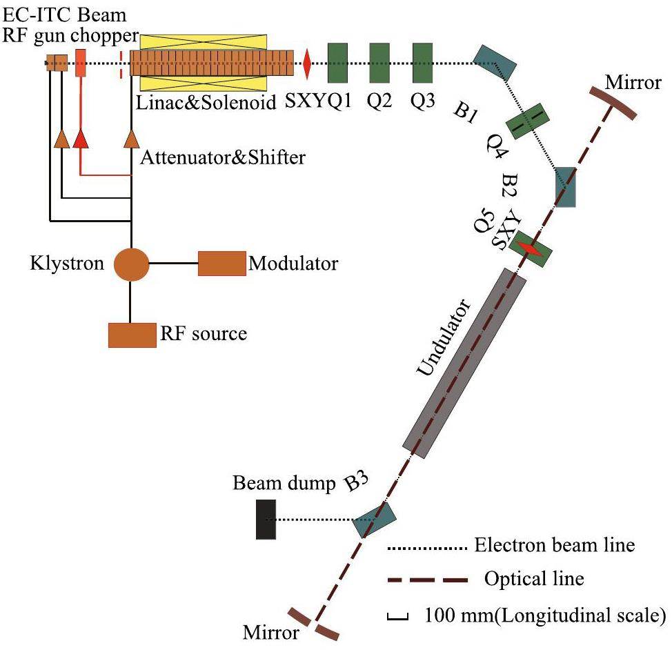
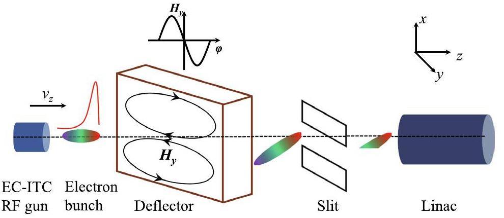
The HUST THz-FEL facility comprises an EC-ITC RF gun, an S-band traveling wave (TW) linac, a double bend achromatic transport line, and a pure permanent magnet type undulator placed in an optical cavity [28]. An improved scheme for removing the tail of the bunch constitutes a beam chopper added to the facility. The layout of HUST THz-FEL is depicted in Fig. 1. A thermionic cathode and two independently tunable cavities comprise the EC-ITC RF gun. The electrons are extracted from the thermionic cathode using a high voltage of 15 kV and then injected into standing wave (SW) cells. The first cell (C1) bunches the pulse beam into multiple bunches with an interval of 350 ps. The second cell (C2) further bunches and accelerates the electron bunch to 2.6 MeV. After the electron gun, a 264-mm-long drift is positioned where the beam chopper system is installed. The beam chopper system consists of a deflector and an x-direction slit, as shown in Fig. 2. A rectangular deflector is chosen for its superiority in fabrication and mode separation when compared to a cylindrical deflector. The deflector is a single-cell cavity with a resonance frequency of 2856 MHz, which is the same as the electron gun and linac. As a result, it can share the same power source. The deflector cavity operates in TM210 mode, with the deflection direction in the x-direction (horizontal direction). The size of the cavity is 117.8 mm× 104 mm × 46.4 mm (x ×y × z) with the quality factor Q=1.56 × 10⁴. The standard waveguide WR-284 (72.14 mm × 34.04 mm) is used to couple RF power into the deflector, and the corresponding waveguide-to-resonator coupling parameter is 1.06. The x-direction slit is positioned at a distance of 137 mm from the exit of the deflector to scrape off tail particles. Particles that successfully pass through the chopper system are then accelerated in the linac. The linac constitutes 24 cells, with the first 20 being accelerating cells and the final four being coaxial loading cells designed to absorb residual power. The beam energy can be varied from 8 to 14 MeV by adjusting the input power and phase of the linac [29]. The solenoid is wrapped around the linac to control the transverse beam size. Five quadrupoles, two dipoles, and two XY combined steering coils make up the transport line [30]. In the middle of the quadrupole Q4, a 3 mm wide x-direction slit is used to cut off the tail particles in the initial design. A variable gap pure permanent magnet undulator with working undulator parameter K ranging from 1.0 to 1.25 is used in the facility [31]. The undulator is placed in an optical cavity, which allows the radiation to be amplified several times. A hole with a radius of 1 mm in the downstream mirror is used to couple out the radiation.
Start-to-end simulation from electron gun to FEL
To investigate the effect of introducing the beam chopper system on the bunch parameters and the radiation performance, we performed a start-to-end simulation from the electron gun to the undulator. PARMELA is used to simulate the beam dynamics of the bunch from the electron gun to the linac. The bunch parameters and FEL performances are not significantly affected when space charge effects in the transport line are not considered. To facilitate the convenient and effective matching of Twiss parameters and orbit correction, ELEGANT is used for simulating the transport line. Space charge effects from the electron gun to the linac are considered in the simulations, while beam loading effects are considered in the linac. The simulation results for each part are presented subsequently.
Beam dynamics of the EC-ITC RF gun
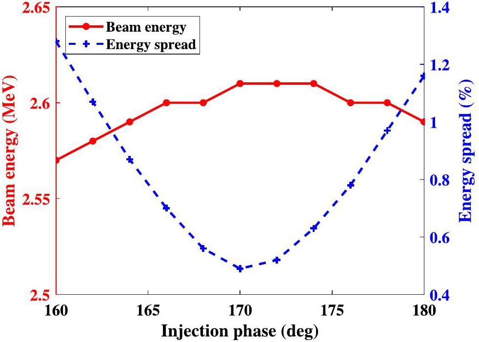
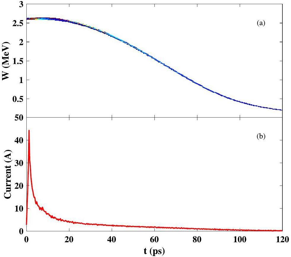
In the simulation of the electron gun section, the injection phase is optimized. The injection phase of C2 must be optimized because the entrance of C1 is the pulse beam while that of C2 is the bunches. The variation of beam energy and energy spread at the exit of the electron gun for different injection phases is shown in Fig. 3. The beam energy reaches a maximum of 2.61 MeV when the injection phase is between 170° and 174°. The energy spread is minimized at an injection phase of 170°. Consequently, 170° is selected as the injection phase of the EC-ITC RF gun for the simulation. The longitudinal phase space and current profile of the bunch at the exit of the electron gun are shown in Fig. 4. The bunch has a long tail, and tail particles have lower energy than the head particle. The peak current at the exit of the EC-ITC RF gun is approximately 45 A. The bunch parameters at the exit of the electron gun are shown in Table 1.
| Parameters | Value |
|---|---|
| Micro-pulse repetition rate (MHz) | 2856 |
| Macro-pulse length (μs) | 4 |
| Beam energy (MeV) | 2.61 |
| Energy spread (RMS) (%) | 0.48 |
| Bunch charge (pC) | 351 |
| Emittance in x-direction (mm · mrad) | 12.9 |
| Emittance in y-direction (mm · mrad) | 12.6 |
Optimization of the chopper system
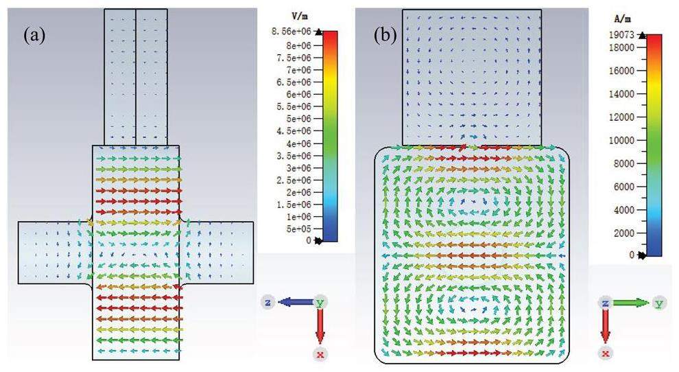
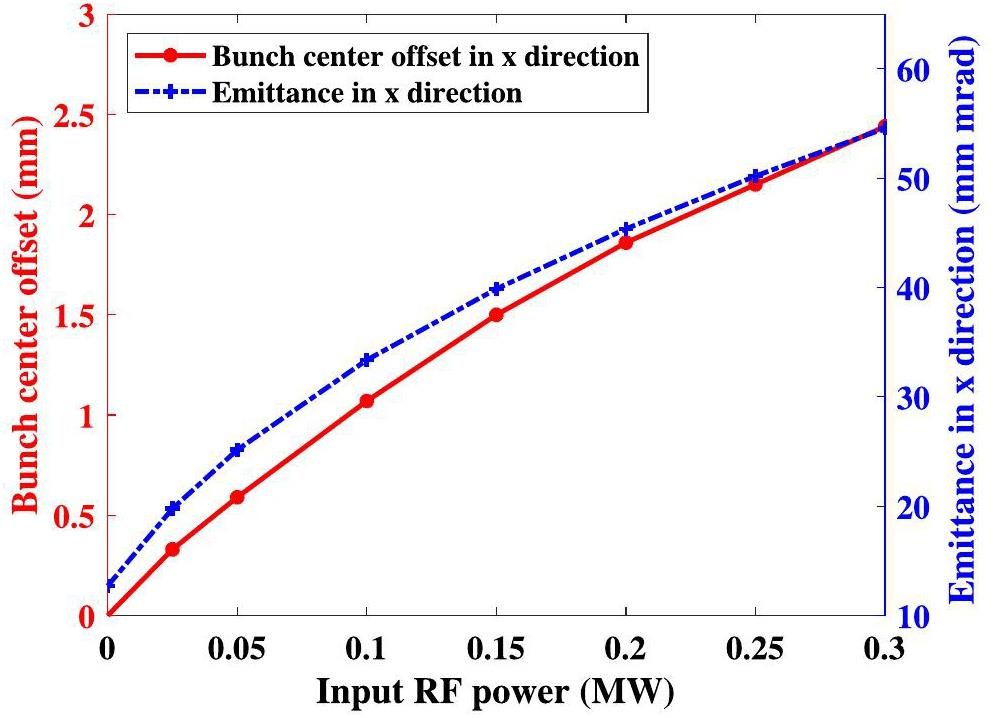
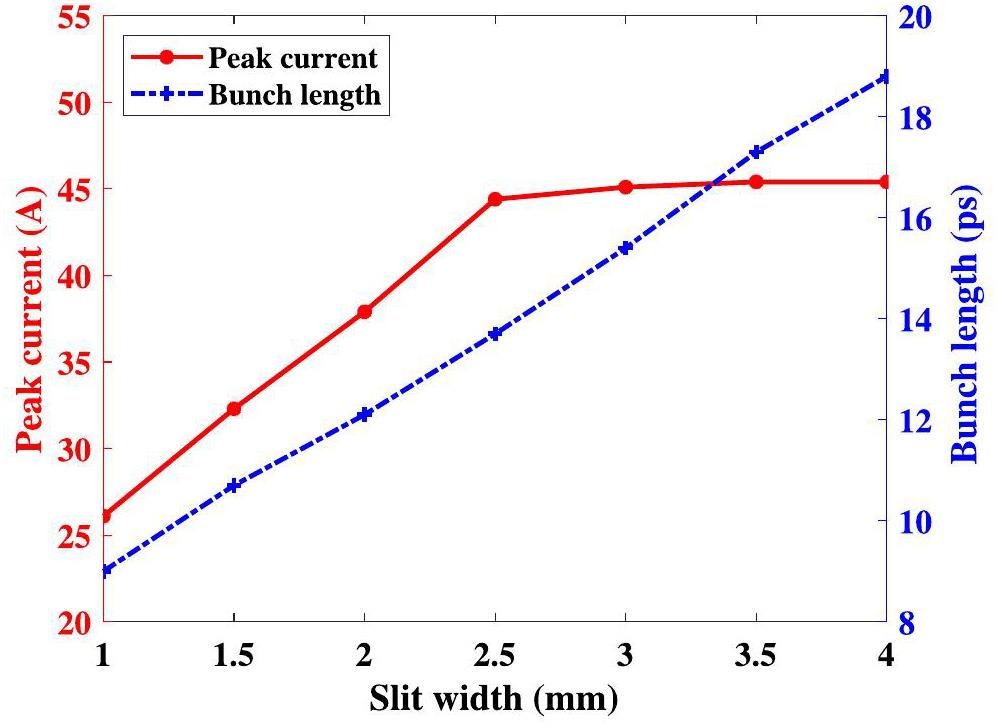
The layout of the chopper system cannot be optimized owing to the limitation presented by the installation space. To improve the beam scraping effect, the input power of the deflector and the width of the slit must be optimized. The electric and magnetic fields of the deflector calculated by CST Microwave Studio 2018 (shown in Fig. 5) are imported into PARMELA to simulate the beam chopper system. For a higher input RF power, the particles in the tail are subjected to a larger deflection force, which can produce a larger transverse offset and are more easily cut off. However, large RF input power also leads to enhanced transverse offset at the center of the bunch and emittance growth, as shown in Fig. 6. At 0.15 MW input power, the offset of the bunch center is 1.5 mm, and the emitance at the exit of the deflector reaches 40 mm mrad. If the input power is greater than 0.15 MW, there are two possible effects: (i) A large transverse offset of the bunch center affects downstream acceleration and transport and is difficult to correct; (ii) A large emitance at the entrance of the undulator affects the radiation performance. Therefore, the input power of the deflector should be below 0.15 MW. For beam scraping, the ideal situation is scraping all the tail particles and not affecting the head of the bunch; however, it is difficult to satisfy both conditions simultaneously. Therefore, the choice of slit width must consider the bunch length and peak current. At an input power of 0.15 MW, the variation of peak current and bunch length at the exit of the chopper system for different slit widths is depicted in Fig. 7. When the slit width is less than 2.5 mm, the peak current decreases as the slit width decreases. This may be because the smaller slit width removes the head particles as well. When the slit width is greater than 2.5 mm, the peak current remains constant, indicating that the head particles are unaffected. From the results of peak currents at different slit widths, the slit width should be chosen to be greater than or equal to 2.5 mm. With an increase in slit width, the bunch length increases, leading to a deterioration in the scraping effect. Inadequate beam scraping leads to a large number of tail particles continuing to enter the linac and being lost in the dispersion section of the transport line. When the slit width is 2.5 mm, more than 5 % of the particles are lost in the dispersion section. At a slit width of 2 mm, the loss of particles in the dispersion section is reduced to 2%. A smaller particle loss in the dispersion section is beneficial to reduce background noise. Therefore, although a slit width of 2.5 mm corresponds to a larger peak current, the slit width is chosen to be 2 mm to decrease the particle loss in the dispersion section. After optimization, the input power of the deflector is 0.15 MW, and the slit width is 2 mm.
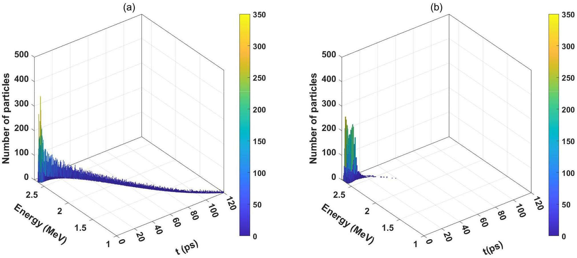
The center of the bunch is shifted by 1.5 mm in the x-direction after passing through the deflector, so the center of the slit must be shifted by the same distance. Approximately 43% of the particles can pass through the chopper system successfully to enter the linac for acceleration. The longitudinal density distribution at the entrance of the linac with and without the beam chopper is shown in Fig. 8. Most of the tail particles are removed through the chopper system, but a few particles remain in the tail. The few remaining tail particles are eventually cut off at the slit located in the middle of the quadrupole Q4. Table 2 depicts the comparison of bunch parameters at the entrance of the linac with and without the chopper system. The bunch length decreases with the chopper in comparison to the non-beam chopper, while other bunch parameters deteriorate. Owing to the effect of the longitudinal electric field in the deflector, the energy spread with the beam chopper system is 1.5 times higher than that without the chopper system. In addition, the x-direction emittance increased to approximately twice the value without the chopper system. The adverse effects introduced by the chopper system can be mitigated by subsequent acceleration and transport.
| Parameter | Without chopper | With chopper |
|---|---|---|
| Beam energy (MeV) | 2.62 | 2.64 |
| Energy spread (RMS) (%) | 0.49 | 0.72 |
| Bunch length (ps) | 72.8 | 12.1 |
| Bunch charge (pC) | 325 pC | 150 |
| Emittance in x-direction (mm · mrad) | 12.6 | 24.7 |
| Emittance in y-direction (mm · mrad) | 12.2 | 11.5 |
Beam dynamics of the linac and transport line
The normalized phase velocity of the linac βφ is designed to be 1. As the velocity of the particles is always less than that of light, all the particles slip backward relative to the RF wave. Therefore, the acceleration phase is generally chosen in the range of 80°–90°, and the phase gradually slips toward the on-crest phase (90°) during the acceleration process. Based on the minimum energy spread, 80° is chosen as the acceleration phase. To obtain the acceleration gradient for each cell, beam loading effects must be analyzed, for which the MPT algorithm can be employed [32, 33]. Beam energies in the range of 8-14 MeV can be obtained at the exit of the linac by adjusting different input RF powers. A beam energy of 14 MeV is used as an example for simulation and analysis. When the input power is 11.1 MW and the accelerating phase is 80°, the accelerating gradient and beam energy of each cell with and without the beam chopper system are shown in Fig. 9. The maximum acceleration gradient is 17.3 MV/m in the first cell, regardless of the presence of a beam chopper system. The acceleration gradient gradually decreases owing to the beam loading effect. The acceleration gradient in the 20th cell is 12.9 MV/m with the beam chopper. However, in the absence of the chopper, several useless tail particles enter the linac, leading to an enhanced beam loading effect. The acceleration gradient is reduced to 8.9 MV/m in the 20th cell. At an input power of 11.1 MW, the bunch can be accelerated to 14 MeV with the chopper, while it is accelerated to 12.3 MeV without the chopper. At the same input power, the energy gain with the beam chopper is 14% higher than the energy gain without the beam chopper. Fig. 10 shows the beam loss during acceleration with and without the chopper system. Without the beam chopper system, approximately 24 pC bunch charge is lost in the linac, risking the safe operation of the linac. When equipped with a beam chopper, there is no beam loss. Consequently, the introduction of the beam chopper system not only saves the linac input power but also reduces the loss of particles in the acceleration process. The solenoid surrounding the linac introduces strong coupling in the x and y directions. This causes emittance conversion in the x and y directions, resulting in a decrease in the x-direction emittance and an increase in the y-direction emittance. Only the center of the bunch in the x-direction is shifted at the exit of the beam chopper, as shown in Fig. 11(a). However, the introduction of coupling causes a shift in the center of the bunch in both the x and y directions at the exit of the linac, as shown in Fig. 11(b). The bunch center at the exit of the linac is shifted and must be corrected in the transport line. Two xy-directional combination steering coils are used to correct the offset of the bunch center. The first steering coil is placed between the linac exit and the first quadrupole Q1, and the other steering coil is placed at quadrupole Q5. Correction of the transport line and matching of the Twiss parameters are performed using ELEGANT. At an energy of 14 MeV, approximately 2% of the particles are lost at the slit in the transport line. Without a chopper, approximately 50% of the particles are lost in the slit. Therefore, the introduction of the chopper results in a significant reduction of the beam loss in the transport line as well as decreased background noise.
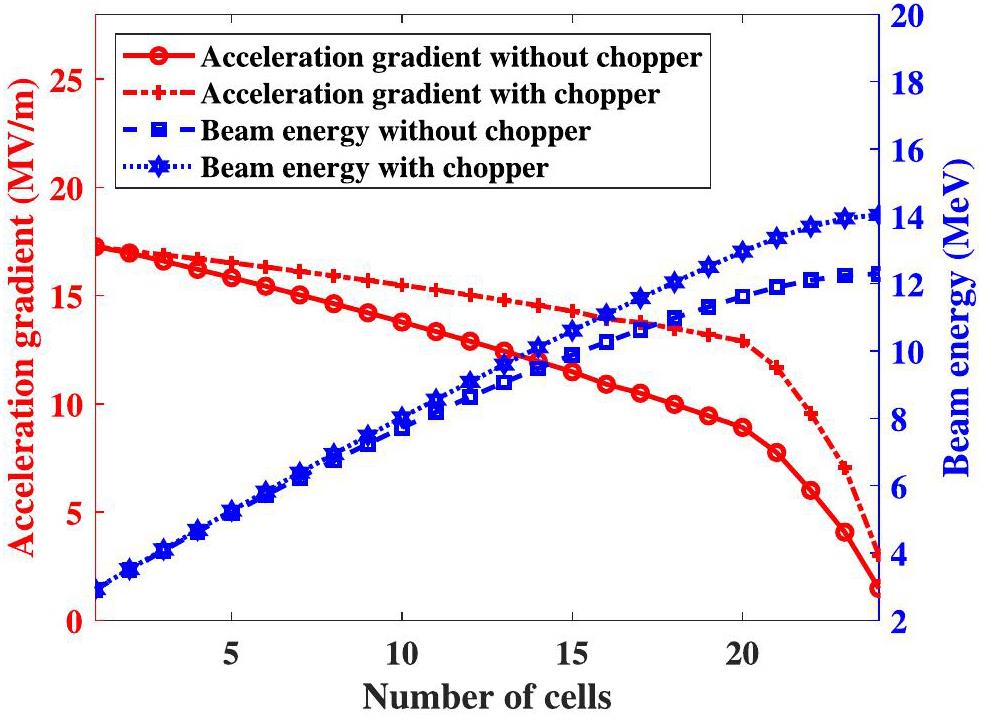
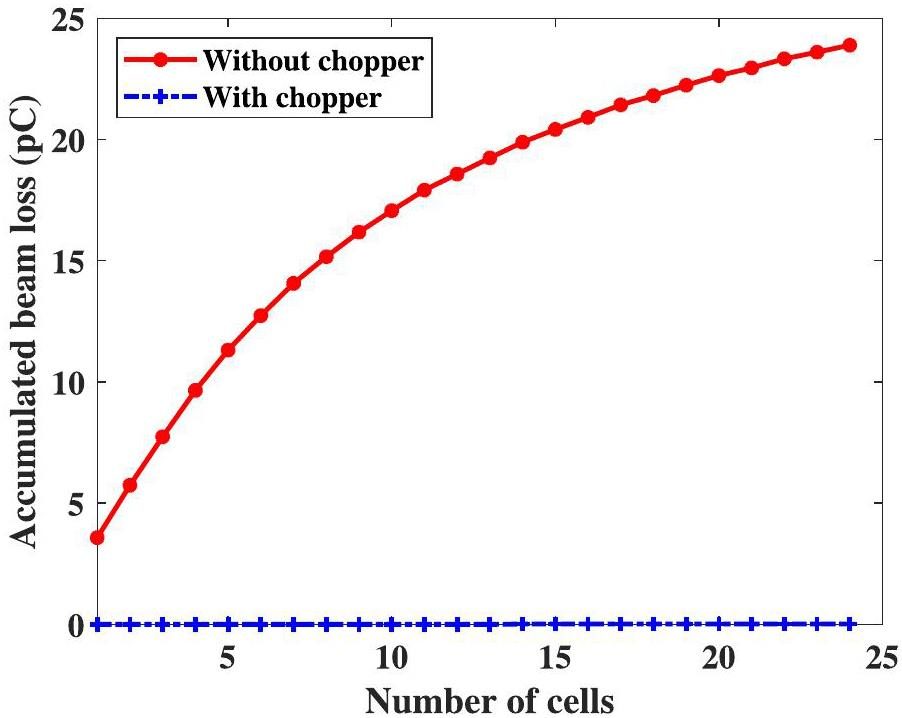
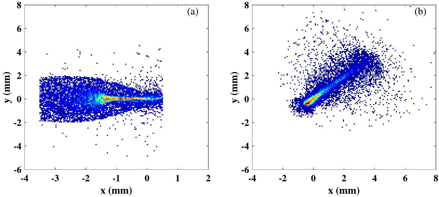
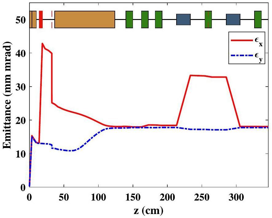
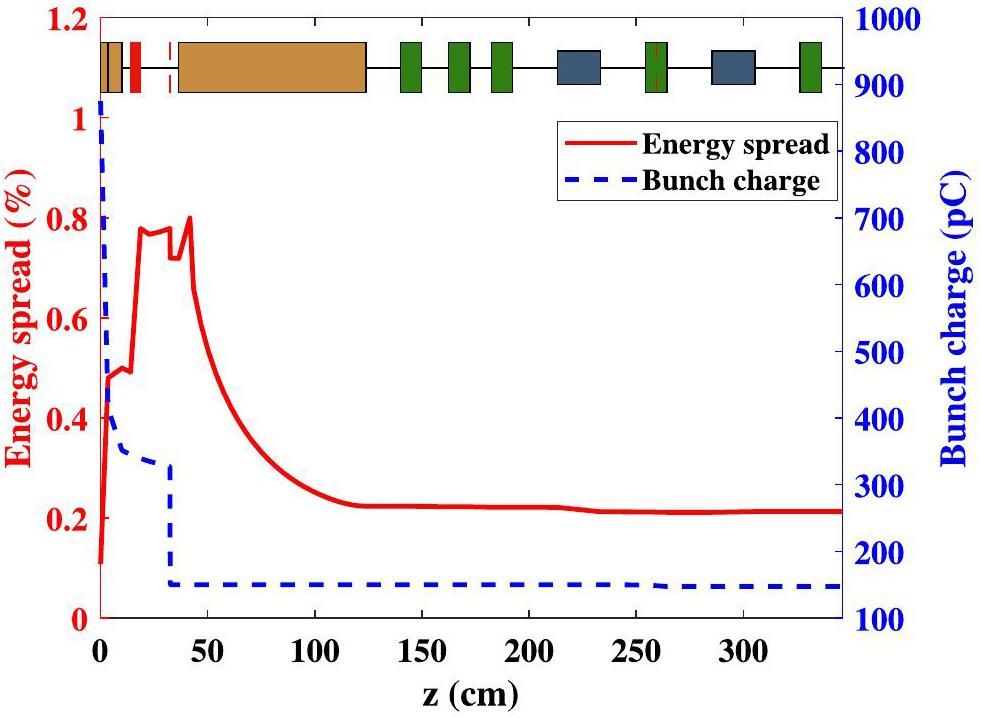
Figure 12 illustrates the variation in emittance from the electron gun to the entrance of the undulator. The x-direction emittance is observed to increase as it passes through the deflector. Subsequently, in the linac, the solenoid causes the x-direction emittance to decrease and the y-direction emittance to increase. The beam charge and energy spread variations from the electron gun to the entrance of the undulator are shown in Fig. 13. The thermionic cathode emits a charge of 875 pC, the capture efficiency of the electron gun is 40%, and the charge at the exit of the electron gun is 351 pC. Subsequently, beam losses occur both in the chopper system and the dispersion region of the transport line. The final charge at the entrance of the undulator is 147 pC. The energy spread increases after passing through the beam chopper and subsequently decreases in the linac. The bunch parameters at the entrance of the undulator are shown in Table 3. Here, the emittance is less than 18 mm mrad, and the peak current is 41.6 A.
| Parameter | Value |
|---|---|
| Beam energy (MeV) | 14 |
| Energy spread (RMS) (%) | 0.21 |
| Bunch length (RMS) (ps) | 3.7 |
| Bunch charge (pC) | 147 |
| Peak current (A) | 41.6 |
| Emittance in x-direction (mm · mrad) | 18.0 |
| Emittance in y-direction (mm · mrad) | 17.8 |
FEL process
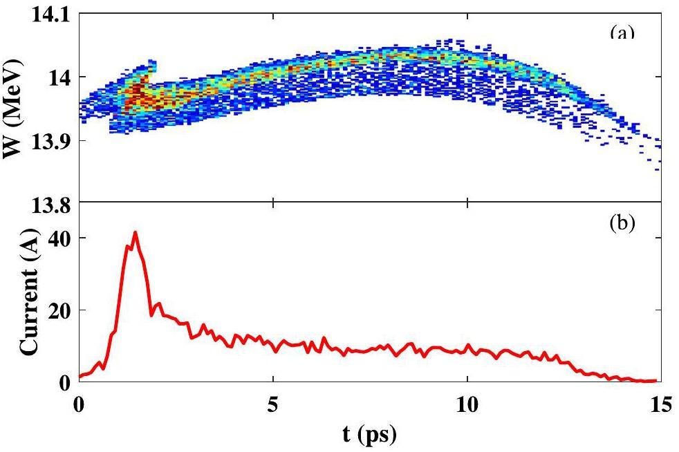
The longitudinal phase space and current profile at the entrance of the undulator are shown in Fig. 14. The six-dimensional particle distribution is imported into GENESIS to simulate the process of generating radiation in the undulator. As it is a low-gain oscillator-type FEL, radiation is amplified multiple times to saturation. OPC is used to simulate the propagation of THz radiation in the optical cavity. The parameters of the undulator and optical cavity are shown in Table 4. The HUST THz-FEL has a macro-pulse length of 4 μs corresponding to a maximum number of 207 passes.
| Parameter | Value |
|---|---|
| Undulator period (mm) | 32 |
| Undulator parameter | 1–1.25 |
| Number of undulator periods | 30 |
| Optical cavity length (m) | 2.887 |
| Reflectivity of mirrors | 0.95 |
| Radius of outcoupling hole (mm) | 1 |
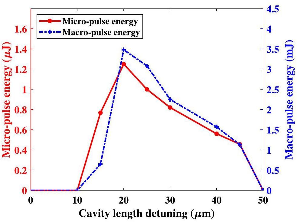
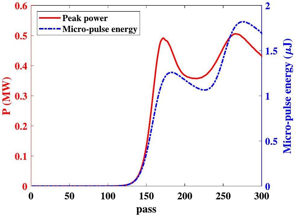
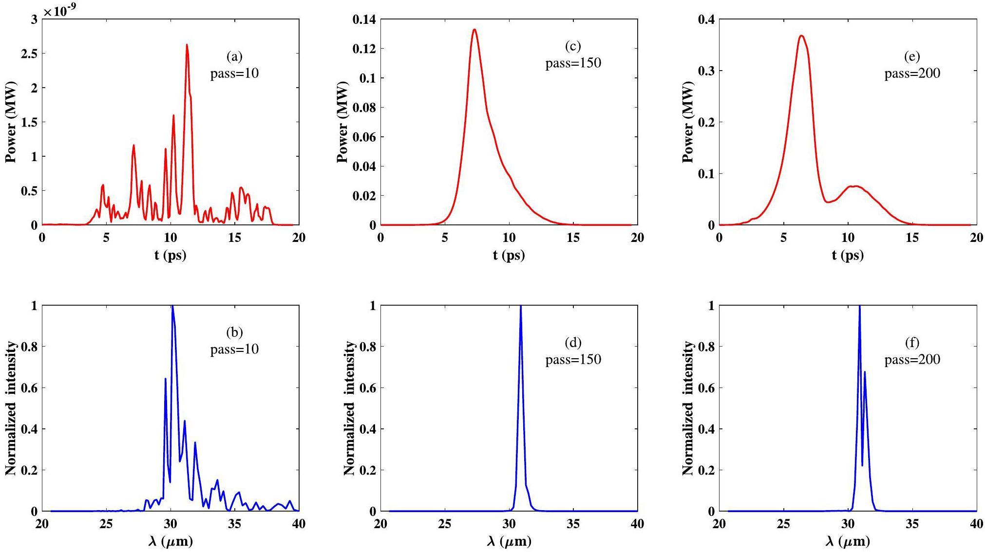
The performance of radiation is analyzed by considering the beam energy of 14 MeV, the undulator parameter of 1, and the corresponding radiation wavelength of 31 m as an example. The variation of micro-pulse and macro-pulse energy for different cavity detunings within 207 passes is shown in Fig. 15. The micro-pulse and macro-pulse energies are maximized at a cavity detuning of 20 m. At a cavity detuning of 10 m and 50 m, the radiation increases more slowly and does not saturate within 207 passes. Therefore, the micro-pulse energy is less than 1 nJ. When the cavity detuning is 0, the radiation almost does not grow, resulting in the micro-pulse being less than 1 nJ. At a cavity detuning of 20 m, the maximum peak power of the optical pulse in the cavity is 25.3 MW, but the maximum peak power of the output is only 0.5 MW. 2% of the power in the optical cavity is coupled out through the hole. Figure 16 shows the variation of peak power and micro-pulse energy for different passes. After 130 passes, the peak power and micro-pulse energy show an exponential increase. After 180 passes, the peak power and micro-pulse energy saturate and begin to oscillate. During the initial few passes, several different frequencies of optical pulse exist in the optical cavity, as shown in Fig. 17 (a) and (b). With the increase in the optical field, only one major longitudinal mode exists in the optical cavity, as shown in Fig. 17 (c) and (d). After the optical field reaches saturation, sideband instability is generated by the coupling of the pulse slip effect and the electronic synchronization oscillation. After saturation, the time structure shows multiple peaks, and the spectrum shows long-wavelength sideband frequencies, as shown in Fig. 17 (e) and (f).
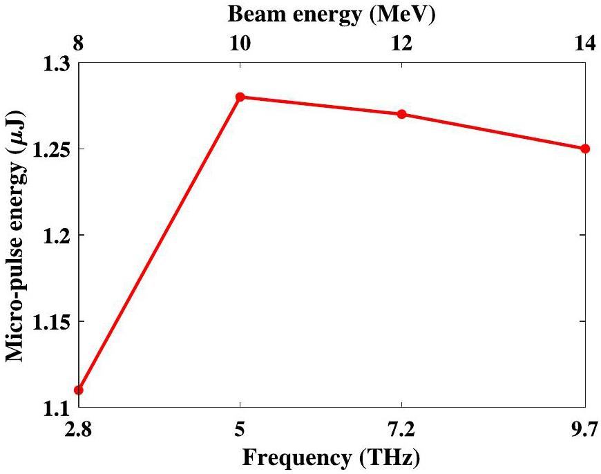
The maximum radiation frequency is 9.7 THz when the undulator parameter is 1 and the beam energy is 14 MeV. The minimum radiation frequency is 2.8 THz when the undulator parameter is 1.25 and the beam energy is 8 MeV. The radiation frequency can be changed by varying the beam energy and the undulator gap. The maximum micro-pulse energies at different radiation frequencies are shown in Fig. 18. In the radiation frequency ranging from 2.8-9.7 THz, the micro-pulse energy is more than 1.1 J. At a radiation frequency of 5 THz, the micro-pulse energy reaches its maximum value of 1.28 μJ.
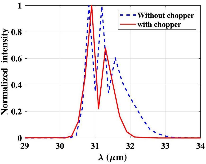
In contrast to not employing a beam chopper, the utilization of a beam chopper results in increased emittance and a decreased peak current at the entrance of the undulator, leading to reduced radiation power at saturation. Additionally, the beam chopper also reduces the bunch length at the entrance of the undulator, which has the advantage of suppressing the sideband instability [34, 35]. The spectrum structures of FEL pulses at saturation with and without the beam chopper are shown in Fig. 19. The spectral structure of the FEL pulse has a shorter bandwidth with the beam chopper. Although the sideband instability can be further suppressed by reducing the slit width to shorten the bunch length, it leads to a significant decrease in the peak current, which affects the radiation power.
Conclusion
The HUST THz-FEL facility has a bunch characterized by a long tail owing to the use of an EC-ITC RF gun. At the beginning of the design, it is considered to remove the tails using x-direction slits in the dispersion region of the transport line. The loss of particles in the dispersion region generates significant background noise, which presents a challenge for THz detection. In addition, it causes several useless tail particles to enter the linac for acceleration, leading to RF power wastage. Additionally, the loss of particles in the dispersion region generates a large amount of background noise. In this paper, we propose an improved method to remove the tail of the bunch by introducing a beam chopper system between the EC-ITC RF gun and linac, which can cut off the tail before entering the linac.
The parameters of the beam chopper system are designed herein. The input power of the deflector is designed to be 0.15 MW, and the x-direction slit width is 2 mm. The introduction of a beam chopper system presents several advantages. First, it saves the RF power of the linac and reduces beam losses in the linac. In addition, the background noise due to particle losses in the dispersion section is reduced. However, the beam chopper system increases the emittance in the x-direction and the energy spread and causes an offset in the center of the bunch. The increase in x-direction emittance is converted into y-direction emittance by a solenoid in the linac. The increase in energy spread is mitigated by the linac. The offset of the center of the bunch is corrected by a steering coil in the transport line. A start-to-end simulation is performed using a beam energy of 14 MeV as an example. The radiation performance is analyzed for a radiation frequency of 31 μm and a cavity length detuning of 20 μm. After the radiation reaches saturation, frequency sidebands appear owing to sideband instability effects. Furthermore, compared with no beam chopper, the utilization of a beam chopper has the advantage of suppressing the sideband instability. Finally, the beam energy and the undulator gap are varied to obtain micro-pulse energies with radiation frequencies in the range of 2.8-9.7 THz. The micro-pulse energy is greater than 1.1 μJ in the frequency range of 2.8-9.7 THz. At a radiation frequency of 5 THz, the micro-pulse energy reaches its maximum value of 1.28 μJ.
Terahertz topological photonics for on-chip communication
. Nat. Photonics 14, 446-451 (2020). https://doi.org/10.1038/s41566-020-0618-9Subwavelength terahertz imaging via virtual superlensing in the radiating near field
. Nat. Commun. 14, 6393 (2023). https://doi.org/10.1038/s41467-023-41949-5Terahertz time-domain spectroscopy
. Nat. Rev. Methods Primers 3, 48 (2023). https://doi.org/10.1038/s43586-023-00232-zInvestigating the function and design of molecular materials through terahertz vibrational spectroscopy
. Nat. Rev. Chem. 7, 480-495 (2023). https://doi.org/10.1038/s41570-023-00487-wBiomedical applications of terahertz spectroscopy and imaging
. Trends in Biotechnol. 34, 810-824 (2016). https://doi.org/10.1016/j.tibtech.2016.04.008Carrier dynamics in semiconductors studied with time-resolved terahertz spectroscopy
. Rev. Mod. Phys. 83, 543-586 (2011). https://doi.org/10.1103/RevModPhys.83.543Terahertz-driven phonon upconversion in SrTiO3
. Nat. Phys. 15, 387-392 (2011). https://doi.org/10.1038/s41567-018-0408-1Review of fully coherent free-electron lasers
. Nucl. Sci. Tech. 29, 160 (2018). https://doi.org/10.1007/s41365-018-0490-1High-field high-repetition-rate sources for the coherent THz control of matter
. Sci. Rep. 6, 22256 (2016). https://doi.org/10.1038/srep22256Design of a pre-bunched THz free electron laser
. Particles 1 267-278 (2018). https://doi.org/10.3390/particles1010021Widely tunable electron bunch trains for the generation of high-power narrowband 1–10 Thz radiation
. Nat. Photon. 17, 259-263 (2023). https://doi.org/10.1038/s41566-022-01131-7Commissioning the photocathode radio frequency gun: a candidate electron source for Hefei Advanced Light Facility
. Nucl. Sci. Tech. 33, 23 (2022). https://doi.org/10.1007/s41365-022-01000-6Hefei infrared free-electron laser facility
. Chinese J. Lasers 48,The new IR and THz FEL facility at the Fritz Haber Institute in Berlin
. Proc. of SPIE 9512,Development of a novel thermionic rf electron gun applied on a compact Thz-fel facility
. Nucl. Instrum. Methods Phys. Res. Sect. A 887 1-6 (2018). https://doi.org/10.1016/j.nima.2017.12.070Design, construction and measurements of an alpha magnet as a solution for compact bunch compressor for the electron beam from thermionic RF Gun
. J. Instrum. 13,Electron beam dynamics in the 3D magnetic field of alpha magnet at the PBP-CMU Electron Linac Laboratory
. Nucl. Instrum. Methods Phys. Res. Sect. A 916, 102-115 (2019). https://doi.org/10.1016/j.nima.2018.11.034Gigahertz repetition rate thermionic electron gun concept
. Phys. Rev. Accel. Beams 22,RF chopper for prebunched radioactive ion beams
,Design of rf chopper system for improving beam quality in fel injector with thermionic gun
. Nucl. Instrum. Methods Phys. Res. Sect. A 755 78-84 (2014). https://doi.org/10.1016/j.nima.2014.04.048Design of a multipurpose rf deflector system applied in a compact linac
. Nucl. Instrum. Methods Phys. Res. Sect. A 988Start-to-end simulation of x-ray radiation of a next generation light source using the real number of electrons
. Phys. Rev. ST Accel. Beams 17,Start-to-end simulation of the shot-noise driven microbunching instability experiment at the linac coherent light source
. Phys. Rev. Accel. Beams 20,Genesis 1.3: a fully 3d time-dependent fel simulation code
. Nucl. Instrum. Methods Phys. Res. Sect. A 429 243-248 (1999). https://doi.org/10.1016/S0168-9002(99)00114-XDesign considerations of a planar undulator applied in a terahertz fel oscillator
. Nucl. Instrum. Methods Phys. Res. Sect. A 727 90-96 (2013). https://doi.org/10.1016/j.nima.2013.06.011RF conditioning and breakdown analysis of a traveling wave linac with collinear load cells
. Phys. Rev. Accel. Beams 21,Optimization of the lattice function in the planar undulator applied for terahertz fel oscillators
. Chin. Phys. C 38,Optical alignment and tuning system for the hust thz-fel
. Nucl. Instrum. Methods Phys. Res., Sect. A 837 58-62 (2016). https://doi.org/10.1016/j.nima.2016.08.043A novel method for rigorously analyzing beam loading effect based on the macro-particle model
. Chin. Phys. Lett. 31Analysis of the beam loading effect in a compact linac with long bunch tails
. Nucl. Instrum. Methods Phys. Res. Sect. A 1051Deep saturated Free Electron Laser oscillators and frozen spikes
. Nucl. Instrum. Methods Phys. Res., Sect. A 834 108-117 (2016). https://doi.org/10.1016/j.nima.2016.07.047Proposal of an operation mode of FELiChEM for generating high-power ultra-short infrared FEL pulses
. Nucl. Instrum. Methods Phys. Res. Sect. A 984The authors declare that they have no competing interests.


