Introduction
Superconducting magnets are widely used in energy, electric power, transportation, medicine, and other fields [1]. NbTi and Nb3Sn are two of the most commonly used materials in superconducting tokamak fusion devices [2-5], which are cooled to temperatures of several K using liquid helium to achieve a superconducting state. However, during device operation, the superconducting magnet is likely to be disturbed by various factors such as mechanical vibrations, thermal disturbances, electromagnetic disturbances, flux jumps, neutron irradiation effects, and chemical corrosion. These types of disturbances may alter the superconducting-material composition as well as its microscopic or macroscopic structure, resulting in the degradation of the superconducting performance of the conductor [6].
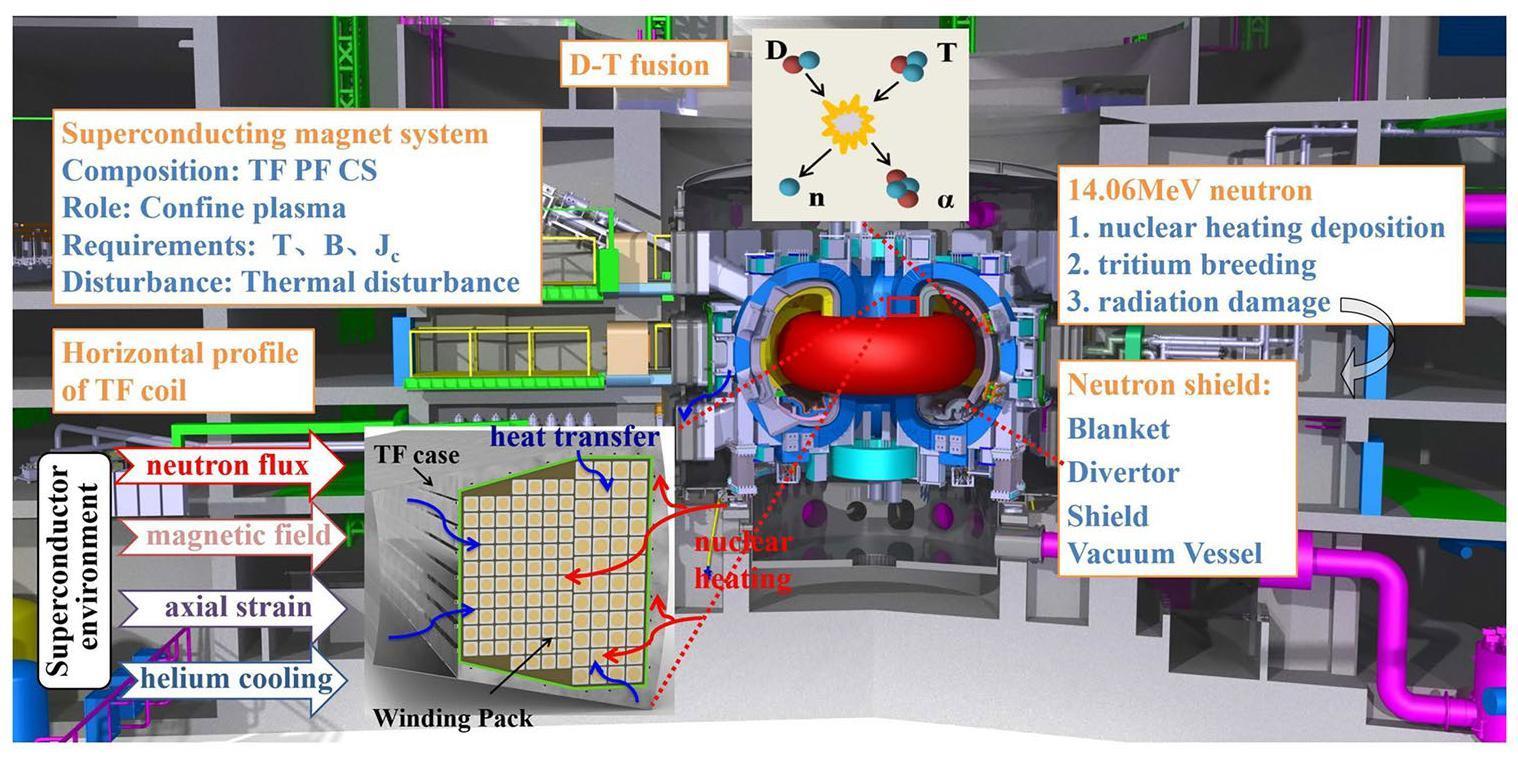
A superconducting magnet system is integral to a tokamak fusion reactor and comprises toroidal field (TF) coils, poloidal field (PF) coils, and a central solenoid (CS) [7]. During normal reactor operation, diverse thermal disturbances affect TF coils, with nuclear heating due to D-T neutrons playing a significant role [8, 9]. D-T fusion releases 4.52 MeV α particles and 14.06 MeV neutrons. While α particles are confined by magnetic fields, neutrons (electrically neutral) travel outward from the plasma area, interacting with local materials and leading to nuclear thermal deposition. Neutron–nucleus collisions within windings cause radiation damage, which degrades the material properties when accumulated [10, 11]. Hence, providing appropriate neutron shielding and cooling for superconducting magnet systems is crucial. Despite the substantial reduction in neutron flux via shielding materials such as blankets, divertors, shields, and vacuum vessels [12-14], nuclear thermal deposition and neutron-irradiation effects remain substantial, necessitating a comprehensive stability analysis. In thermal hydraulics, the cooling system must efficiently extract heat from the magnet system. Excessive heat deposition that surpasses the capacity of the cooling system leads to a localized rise in conductor temperature and eventual quenching [15]. Unlike PF and CS, TF coils primarily generate the main magnetic field; however, they are exposed to the highest neutron-flux levels [16]. Hence, rigorous neutronics and thermal-hydraulic analyses are imperative for TF coils to evaluate nuclear-heating disturbances and predict conductor temperature margins.
Accurate assessment of the heat load on the TF coils requires the consideration of diverse factors such as nuclear heating, heat transfer from the case, cooling conditions, magnetic fields, and strain. In the past century, projects such as ITER, JT-60SA, EU-DEMO, K-DEMO, and CFETR have conducted detailed calculations and analyses, frequently integrating neutronics and thermal-hydraulic methods [17-26]. These methods have been optimized in several respects. JT-60SA’s nuclear-heating analysis [27] incorporated nuclear heating, coil-case heat transfer, and AC losses, noting a negligible AC-loss contribution during normal operation. Similarly, ITER’s TF temperature-margin analysis [28] considered nuclear heating and heat transfer from the coil case, assessing the central and side pancakes under varying nuclear-heat load scenarios. DEMO [29, 30] and CFETR [9] employed two- and one-dimensional (2D/1D) thermal-hydraulic calculations, considering the magnetic-field distribution, nuclear heating, and coil-case heat transfer.
In this study, an improved analysis method combining neutronics and thermal hydraulics is proposed to evaluate the influence of nuclear heating on the temperature of TF coils in a tokamak fusion reactor. Compared with the traditional method, the proposed method makes the following two improvements:
1. The heterogeneous parametric TF model accurately captures the nuclear-heat distribution in cables, insulators, and other components. As fusion-reactor magnet-system designs evolve, this method adopts a parametric-modeling approach, enabling the rapid adjustment of key parameters (such as cable diameter) for the quick generation of neutronics-calculation models, thereby saving time and enhancing accuracy.
2. Compared with the conductor with the maximum magnetic field, highest nuclear heating, and poor cooling conditions, only one or two cooling circuits are selected for thermal-hydraulics analysis.
This method aims to precisely and efficiently assess the temperature margins during normal tokamak operations. Figure 1 illustrates the TF-coil operating environment in a fusion reactor, and Fig. 2 outlines the proposed technical approach. The detailed steps are as follows.
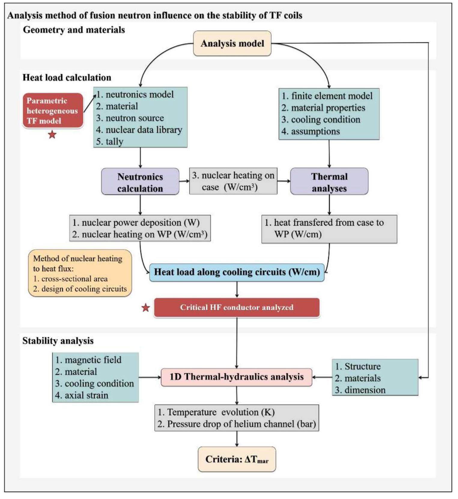
We define the analysis model, which encompasses the reference CAD model, materials, and superconducting strand scaling parameters of the fusion reactor. A corresponding neutronics parametric heterogeneous model is created based on the CAD model, establishing cable, insulator, and jacket structures within the winding pack (WP) area. The impact of the improved method on the heat-load accuracy is presented in Sect. 3.1. Neutron sources can be constructed using the plasma parameters (Sect. 2.2), and nuclear-data libraries such as ENDF/B [31], JEFF [32], and FENDL [33] are typically employed. The Nb3Sn/NbTi critical currents can be calculated using the scaling-law equations.
Monte Carlo-based neutronics calculations were used to assess the nuclear-heating distribution in TF coils caused by D-T neutrons and secondary photons. TF coils are typically poloidal segmented into several sectors to facilitate the statistical analysis of the nuclear-heating poloidal distribution. The conductor with the maximum nuclear heating was determined considering the radial, poloidal, and toroidal distributions on the WP.
Thermal analysis software was used to calculate the heat transfer from the TF case to the WP using nuclear-heating data. The TF case was divided into a suitable number of poloidal segments, and a 2D finite-element model was employed for the calculation. Different heat-transfer coefficients were applied to different boundaries.
Neutronics calculations were combined with thermal-hydraulic analysis to calculate the heat load along the cooling circuit. The average nuclear-heating density for each turn was computed based on the material-volume proportions. The nuclear-heating density along the cooling circuits (such as HF-1) can be obtained by considering the cross-sectional area of each turn and the arrangement of the cooling circuits.
One cooling circuit was selected for the thermal-hydraulic analysis based on the conductor with the maximum magnetic field, highest nuclear heating, and poor cooling. A thermal-hydraulic analysis was performed considering the total thermal-load, mechanical, cooling, and electromagnetic conditions, and the conductor-temperature evolution was calculated.
This method offers a systematic and comprehensive evaluation of fusion neutron-induced TF-coil thermal stability, involving critical property calculations, neutronics modeling, nuclear-heating and heat-transfer analysis, conductor heat-load assessment, critical cooling-circuit analysis, and final temperature evaluation. The accuracy of the results was greatly improved with the elaborate neutronics model, and counting the radial and toroidal nuclear-heating distributions was more convenient. Heterogeneous parametric neutronics models significantly boost the accuracy of the results and simplify the model modification process. This method facilitates a precise evaluation of the temperature margins for conductors in the most challenging cooling circuit. Furthermore, it provides insights into optimizing the structure and cooling scheme of fusion-superconducting magnet systems.
Sections 2–4 demonstrate this method by analyzing TF-coil nuclear-heating stability in a tokamak fusion reactor. The major and minor radii of the reactor were 3.6 m and 1.1 m, respectively, with TF magnets generating a peak magnetic field of 13.5 T and central magnetic field of 6.5 T. The reactor was operated in the steady-state and transient modes. For the steady state, the fusion power was 40 MW with a 1000 s plasma pulse. For the transient modes, the fusion power was 180 MW with a 10 s plasma pulse. The data were sourced from the corresponding magnet-design reports.
Analysis model
Conductor and strand parameters
The TF-magnet system comprises 16 TF coils, each containing 126 turns. It carries a nominal current of 55 kA and provides a 6.5 T magnetic field at the plasma center to confine the plasma. The WP is enclosed in a stainless-steel case. The geometry of the cable-in-conduit conductors (CICCs) is shown in Fig. 3(a). The WP can be divided into two sub-WPs: high-field (HF) and low-field (LF). The HF WP comprises six double pancakes (DPs), in which a high-Jc Nb3Sn strand is selected, whereas the LF adopts an ITER-like Nb3Sn strand. The structure of the conductor includes an insulator, jacket, cable, and helium channel, corresponding to gray, white, yellow, and black, respectively, in Fig. 3(a). SS316LN was used for the TF case and jacket, and G10 was used as an insulator [34].
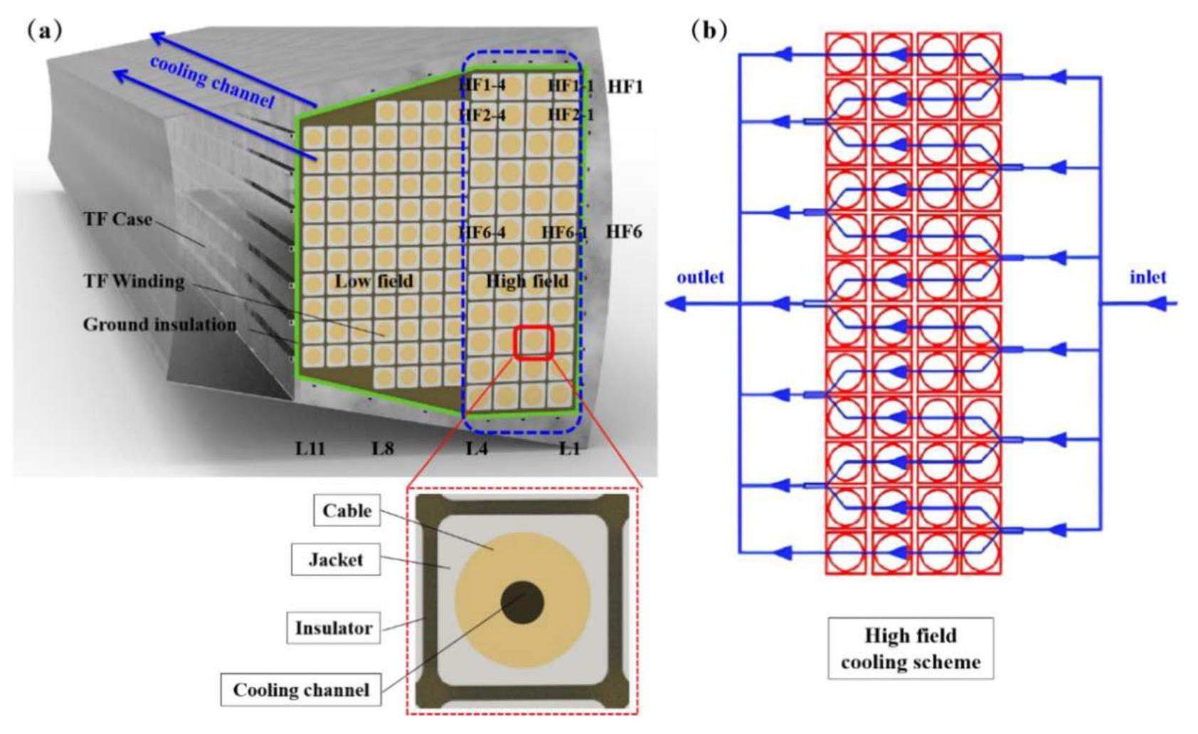
Figure 3(b) shows the horizontal profile of the cooling scheme for the HF WP. Six parallel cooling circuits are included, with two pancakes set as one cooling circuit. The length of each cooling circuit was approximately 80 . Helium flowed in opposite poloidal directions in two adjacent cooling circuits. The primary parameters of the conductor and strands are listed in Table 1.
| HF WP conductor | LF WP conductor | |
|---|---|---|
| Strand type | OST-E2013 | ITER-like |
| Strand diam. (mm) | 0.82 | 0.82 |
| No. of SC | 720 | 450 |
| No. of Cu | 420 | 300 |
| Cable layout | (2SC+1Cu)×3×4×5×6+1core | ((2SC+1Cu) ×3×3×5+1core)×5 |
| Cu core layout | 3×4×5 | 3×5 |
| Cable pattern | STP | STP |
| Jacket material | 316LN | 316LN |
| Void fraction | ∼30% | ∼30% |
| Cable diam.(mm) | 34.3 | 27.6 |
| Axial strain | -0.6% | -0.6% |
The critical current in the Nb3Sn composites was calculated according to the scaling law of [35]. The scaling parameters of the Nb3Sn strand are listed in Table 2.
| Parameters | High-Jc Nb3Sn | ITER-like Nb3Sn |
|---|---|---|
| 49.23 | 49.00 | |
| 7.70 | 0.300 | |
| 0.32% | 0.312% | |
| -0.07% | 0.059% | |
| 31.68 | 33.24 | |
| 16.53 | 16.34 | |
| C(AT) | 58158 | 21700 |
| p | 0.60 | 0.593 |
| q | 2.17 | 2.156 |
Neutronics model
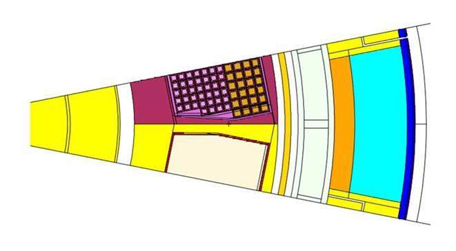
Considering the symmetry of the fusion reactor, a sector spanning 22.5 degrees enclosed by reflective planes was used for the Monte Carlo neutronics simulations. The model encompasses components such as the blanket, divertor, vacuum vessel, thermal shield, TF coils, PF coil, central solenoid, ports, and cryostat.
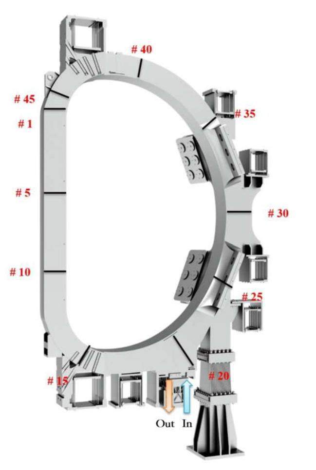
The blanket, divertor, and vacuum vessel collectively contribute to neutron shielding, with the blanket assuming the primary role of shielding neutrons in the magnet system. As illustrated in Fig. 4, the TF coils were divided into 45 poloidal sectors arranged counterclockwise from the inboard leg. Sectors 12–23 are positioned at the rear of the divertor, whereas the remaining sectors are situated at the rear of the blanket. Sector 19 houses the helium inlet, and Sector 18 contains the outlet, as shown in the diagram.
Owing to the intricate nature of the WP and the substantial number of torus surfaces, significant effort has been invested in neutron modeling using the constructive solid geometry (CSG) method. The complexity of modeling in this area is typically addressed by employing a hierarchical structure or homogeneous model. In line with the design of the TF coils, this study modeled a heterogeneous parametric WP model with a cable, stainless-steel jacket, and insulator structure.
However, the simulation faces limitations owing to the constrained capabilities of the Monte Carlo computing code MCNP [36, 37] when applied to a multitude of torus surfaces. To maximally enhance model accuracy, an “approximate rectangular cross-section" was employed as a substitute for the “circular cross-section," determined based on material-volume proportions of the turns.
Based on Fig. 5, both a homogeneous WP and a more intricate WP configuration were constructed to facilitate a comparison for the precision enhancement.
The probability distribution for sampling 14.1 MeV neutrons is defined as follows:
During this phase, the principal parameters of the conductor and strand are initially established, and the critical current in the Nb3Sn composites is computed using scaling-law equations. Subsequently, a heterogeneous parametric neutronics model and neutron source were constructed. These models were based on the reference CAD model and plasma parameters, respectively.
Heat load
The cumulative heat load on the conductors comprised nuclear deposition (from both neutrons and photons emitted by D-T reactions) and heat transferred from the case to the WP. A higher nuclear deposition on the central turn than on the corner turn can be reasonably anticipated. However, the situation becomes more intricate when the heat transfer from the case is considered. The influence of displacement and gaps on the heat transfer in the TF coils under Lorentz forces during normal operation must be considered [16]. Previous research [39] has highlighted that corner turns experience a notably greater heat-transfer load than central turns. Consequently, a precise statistical analysis of both toroidal and radial heat load profiles is essential.
By comparing the magnitudes of the nuclear heat and the heat transferred across various turns, cooling circuit capable of effectively managing the maximum heat load may be identified.
Nuclear heating
Nuclear heating was evaluated using the Monte Carlo particle-transport code MCNP v5.1.6 with the FENDL 3.1d nuclear-data library. Assuming a fusion power of 40 MW, the corresponding D-T neutron-emission rate was set as 1.42×10¹⁹ s-1. A bi-dimensional (radial and poloidal) discrete neutron source was employed to characterize the spatial distribution of D-T neutrons. By employing the neutronics model above, the nuclear-heating distributions within the TF coils were calculated based on 1010 neutron histories. To enhance the statistical efficiency of the Monte Carlo simulations for shielding calculations, an importance-based variance-reduction technique was implemented to ensure satisfactory results and statistics, which generally remained below 0.5%.
Table 3 outlines the nuclear-power deposition in the TF coils. The overall TF-coil deposition amounts to 17.86 kW, with the case contributing 51.7% and WP providing 48.3% of this total. Additionally, a comparison was made between the nuclear-power deposition at the rear of the blanket and divertor with the aim of evaluating the neutron-shielding effectiveness. Notably, the total nuclear heat of TF coils obtained through the homogenized model reached 17.46 kW, exhibiting a relative error of 2.2% compared with the detailed heterogeneous model. Considering the statistical-count error (below 0.5%), the influence of the model accuracy on the comprehensive nuclear heat cannot be dismissed.
| Poloidal sector | WP-cable | WP-jacket | WP-insulator | Case | Total |
|---|---|---|---|---|---|
| BLK rear | 2.25 | 2.38 | 0.77 | 4.93 | 10.34 |
| DIV rear | 1.28 | 1.41 | 0.52 | 4.31 | 7.52 |
| Total | 3.53 | 3.79 | 1.30 | 9.24 | 17.86 |
| Percent | 19.76% | 21.22% | 7.28% | 51.74% | 100% |
To further assess the precision enhancement of the heterogeneous model in terms of TF nuclear heating, a comparison of two typical cross-sections is shown in Table 4: one at the inboard middle plane (IB) and the other at the outboard middle plane (OB). The differences in the nuclear-heating densities of the cable, jacket, and insulator in the IB were -16.2%, 7.3%, and 2.7%, respectively. Significant differences were observed in the OB. This is because in the heterogeneous model, only neutrons passing through the case, jacket, and insulation interacted with the cable material, leading to the observed variations. In the thermal-stability analysis of the TF-magnet system, the precision of the cable in the heterogeneous model improved by more than 12%. This improvement is crucial for subsequent heat-loading and temperature-margin assessments in the thermal-hydraulic nuclear context.
| Model | IB-cable | IB-jacket | IB-insulator | OB-cable | OB-jacket | OB-insulator |
|---|---|---|---|---|---|---|
| Hetero. model | 7.57 × 10⁻⁴ | 9.84 × 10⁻⁴ | 3.56 × 10⁻⁴ | 1.63 × 10⁻⁴ | 2.09 × 10⁻⁴ | 8.61 × 10⁻⁵ |
| Homo. model | 8.80 × 10⁻⁴ | 9.12 × 10⁻⁴ | 3.46 × 10⁻⁴ | 1.83 × 10⁻⁴ | 1.95 × 10⁻⁴ | 8.32 × 10⁻⁵ |
| Difference | -16.20% | 7.30% | 2.70% | -12.50% | 6.70% | 3.40% |
Figure 6 shows the polar distribution of the WP nuclear-heating density within HF conductor layer 1. The average nuclear-heating densities of the cables, jackets, and insulators were 3.35×10⁻⁴ W/cm3, 4.34×10⁻⁴ W/cm3, and 1.63×10⁻⁴ W/cm3, respectively. For the nuclear-heating density, the insulator displayed the lowest value, the cable registered approximately 2.06 times the value of the insulator, and the jacket demonstrated a nuclear-heating density approximately 2.67 times greater than that of the insulator. The highest value was observed on the upper side of the IB (Sector 5). Furthermore, the conductor (Sector 16–18) at the rear of the divertor exhibited an elevated nuclear-heating density, suggesting its potential for divertor-shielding enhancement. Neutron fluxes in proximity to the middle plane and port tended to be high, accompanied by corresponding nuclear-heating densities on the rear side of TF coils.
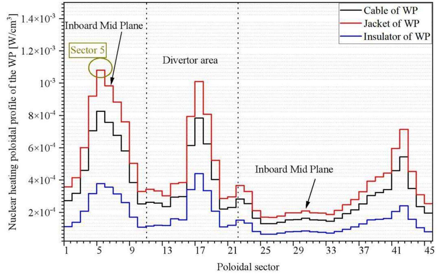
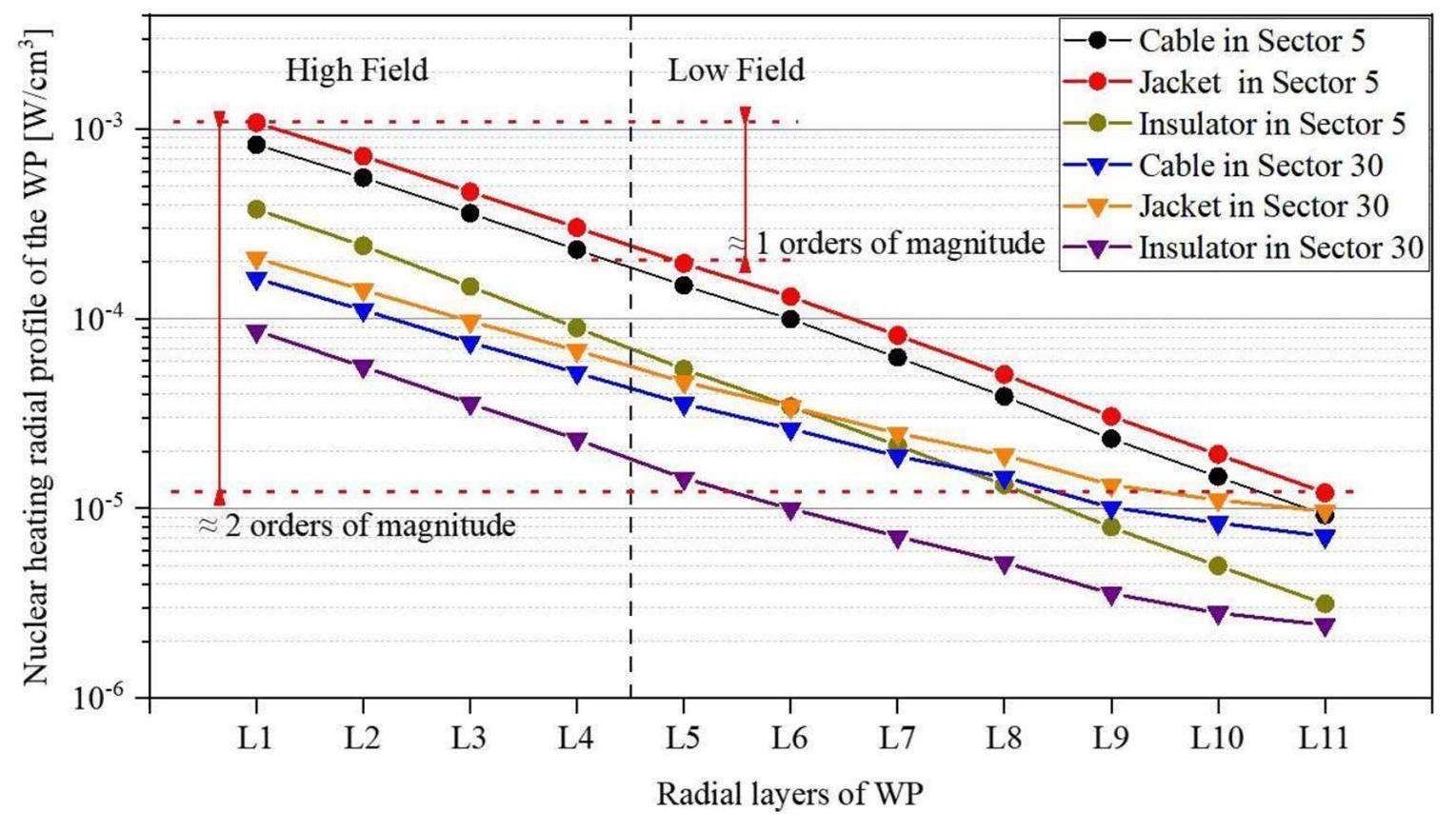
Figure 7 illustrates the exponential decay of the nuclear-heating density along the radial direction for the WP in Sectors 5 (IB) and 30 (OB). Comparing the rear layer in the HF with the front layer at the IB, the value decreased by 3.56 times in the HF and by 16.26 times in the LF. Similar comparisons with the OB front layer showed a 3.14 times decrease in the HF and only a 4.99 times decrease in the LF. Notably, the nuclear-heating density in the HF surpassed that in the LF by an order of magnitude, highlighting the preference for the HF in subsequent analyses.
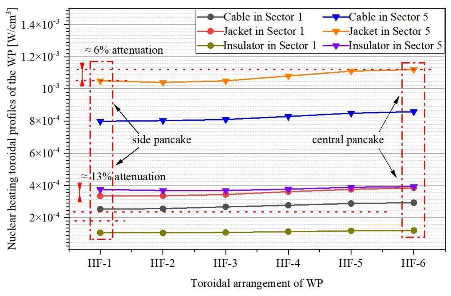
The statistical assessment of the nuclear-heating toroidal profile in the HF is important for selecting the optimal cooling circuit for thermal-hydraulic analysis. As shown in Fig. 8, a comparison between Sectors 1 and 5 revealed that, in Sector 1, the cable, jacket, and insulator values in HF-6 (central pancakes) were 13%–16% higher than those in HF-1 and HF-2 (side pancake). A similar trend was observed in Sector 5, with an increase of approximately 5%–8%. As expected, the central turn exhibited a higher nuclear deposition than the corner turn; however, the discrepancy was not notable.
Heat transferred from case to coil
The TF case comprised U-shaped enclosures (AU and BU) and cover plates (AP and BP). Both AU and BU featured 22 cooling channels, whereas AP and BP had eight cooling channels each. The mass-flow rate for each cooling channel was 2.7 g/s, with an inlet pressure of 6 bar and inlet temperature of 4.2 K. During operation with a pulse duration of 1000 s, a steady state for heat transfer between the case and conductor was achieved. However, in the case of a pulse duration of 10 s, heat transfer was disregarded. Ansys 19.0 was utilized to conduct a 2D heat-transfer analysis, relying on the nuclear-heating results obtained from MCNP for the case at 40 MW. Owing to the inward compression resulting from the centering force on the WP, a millimeter-sized gap was formed between the inner side of the WP and the case [16]. Consequently, the heat transfer between the case and plasma-side of the WP became limited. An ideal heat transfer between the case and other sides of the WP is assumed considering the isotropic material properties. The heat-transfer coefficient was calculated using the following equation:
The finite-element model of the TF case for the heat-transfer calculation was discretized into 45 2D sectors in the poloidal direction. As indicated in Table 5, the heat flux transferred from the TF case to the conductors was calculated. Notably, corner turns exhibited a significantly higher heat flux than central turns. In the toroidal direction of Sector 5, the heat-flux value in HF 1-1 was approximately 2.5 times greater than those in HF 2-1 and HF 6-1. In the radial direction, the heat-flux values in HF 1-1, HF 2-1, and HF 6-1 surpassed those in the turns of the second layer by a substantial margin.
| Turn | HF 1-1 | HF 1-2 | HF 1-3 | HF 1-4 |
|---|---|---|---|---|
| Heat flux (W/cm) | 8.063 × 10⁻³ | 3.663 × 10⁻³ | 3.223 × 10⁻³ | 3.916 × 10⁻³ |
| Turn | HF 2-1 | HF 2-2 | HF 2-3 | HF 2-4 |
| Heat flux (W/cm) | 3.289 × 10⁻³ | 1.287 × 10⁻³ | 1.287 × 10⁻³ | 1.045 × 10⁻³ |
| Turn | HF 6-1 | HF 6-2 | HF 6-3 | HF 6-4 |
| Heat flux (W/cm) | 3.256 × 10⁻³ | 1.287 × 10⁻³ | 1.287 × 10⁻³ | 1.023 × 10⁻³ |
These outcomes highlight the substantial variation in heat transfer from the case to the coil across different turns, and these values constituted a significant portion of the overall heat load.
Total heat load on conductor
In the subsequent phase, the cumulative heat load absorbed by the conductors along the cooling circuits is quantified. This process can be divided into two steps: first, the average nuclear-heating flux for each turn is calculated based on the material proportion and cross-sectional area of the turn; second, the nuclear heat on HF-1 and HF-6 is determined based on the arrangement of the helium cooling circuits. The calculation of the average nuclear-heating flux is given by Eq. (4), where q and V symbolize nuclear-heating density and the volume proportion of the cable in each turn, respectively. A represents the cross-sectional area of the turn.
In this scenario, the helium inlet and outlet were strategically positioned in Sectors 19 and 18, respectively. Consequently, the heat load along the cooling circuits within each of the four layers (each approximately 4×20 m) was initiated at the heat flux originating from Sector 19 and concluded in Sector 18.
Figure 9 shows the heat load on the conductor along the cooling circuits. HF-6 HT (heat transferred from the case to HF-6) was approximately half that of HF-6 NH (nuclear heating on HF-6). While the nuclear heating on the side pancake (HF-1 NH) was marginally lower than that on the central pancake (HF-6 NH), the heat load transferred from the case (HF-1 HT) significantly surpassed that of the central pancake (HF-6 HT). Thus, HF-1 experienced the highest heat load, followed by HF-6.
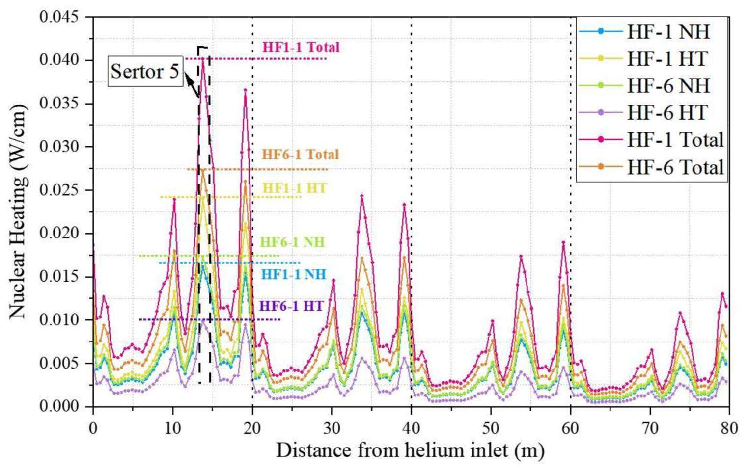
Notably, the analysis did not consider the impact of AC losses on the heat load. Owing to the unique cooling scheme and variations in the heat-transfer coefficient and WP structure, the heat load of the central and side pancakes may differ. Thus, a comprehensive analysis of the maximum heat load that considers both the distribution of nuclear heating and conduction heat of the coil box is imperative.
Furthermore, the conductor heat-loading method can be applied to alternative arrangements of helium cooling circuits. Of particular significance are the TF sector numbers, where the helium inlet and outlet are located, and the poloidal direction of the helium flow.
Thermal-hydraulic analysis
In this phase, the cooling circuits subjected to the peak magnetic field and heat load were examined, and the cooling circuit with the most challenging combined conditions was selected for 1D thermal-hydraulic analysis. The simulation results were obtained using Gandalf [40], a widely used tool for magnet-stability analysis. The input parameters for the thermal-hydraulic analysis are listed in Table 6.
| Parameters | Value |
|---|---|
| Nb3Sn cross section (m2) | 1.90 × 10⁻⁴ |
| Copper cross section (m2) | 4.12 × 10⁻⁴ |
| Jacket cross section (m2) | 6.36 × 10⁻⁴ |
| Insulation cross section (m2) | 2.29 × 10⁻⁴ |
| Helium in Bundle cross section (m2) | 2.94 × 10⁻⁴ |
| Helium in Hole cross section (m2) | 2.83 × 10⁻⁵ |
| Bundle-region hydraulic diameter (m) | 4.74 × 10⁻⁴ |
| Hole-region hydraulic diameter (m) | 6.00 × 10⁻³ |
| Wetted Perimeter between strands and the bundle helium (m) | 2.45 |
| Wetted Perimeter between conductor strands and the jacket (m) | 1.08 × 10⁻² |
| Wetted Perimeter between jacket and the bundle helium (m) | 9.70 × 10⁻² |
| Wetted Perimeter between bundle and the hole helium (m) | 1.88 × 10⁻² |
| Percentage perforation | 0.1 |
The choice of the cooling circuit is depicted in Fig. 10. HF1-1 and HF12-1 experienced a peak heat load; HF6-1 and HF7-1 encountered a peak magnetic field and high heat load; and HF7-1 represented the turn facing the peak magnetic field under poor cooling conditions. This is because of the clockwise helium flow in HF6-1 and counterclockwise flow in HF7-1. This caused hydraulic length from Sector 19 (helium inlet) to Sector 5 (peak magnetic field and nuclear heating) in HF7-1 to be longer than that in HF6-1. Considering the magnetic field, heat load, and cooling conditions, HF7 was chosen for the thermal-hydraulic analysis. It comprised four turns, forming an 80-m path.
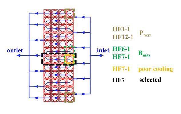
The thermal-hydraulic analysis model comprised four parts: the strands, conduit, bundle helium, and hole helium. The convective heat-transfer calculations were based on a previous study [41]. Adiabatic boundary conditions were applied to the ends of the cables.
Three aspects of TF operating conditions were considered:
(1) Mechanical conditions: The influence of the Lorentz force on the superconducting magnet operation necessitates the consideration of strain. The axial strain of the superconducting strand was assumed to be -0.6% under these calculations.
(2) Cooling conditions: Assumed cooling conditions encompassed an inlet temperature of 4.2 K, pressure of 6.0 bar, and mass-flow rate of 8.0 g/s. The hydraulic length of the HF was approximately 80 m.
(3) Electromagnetic conditions: The conductor carried a steady current of 51.7 kA, resulting in a peak magnetic field of 13.5 T on the WP.
Steady-state mode
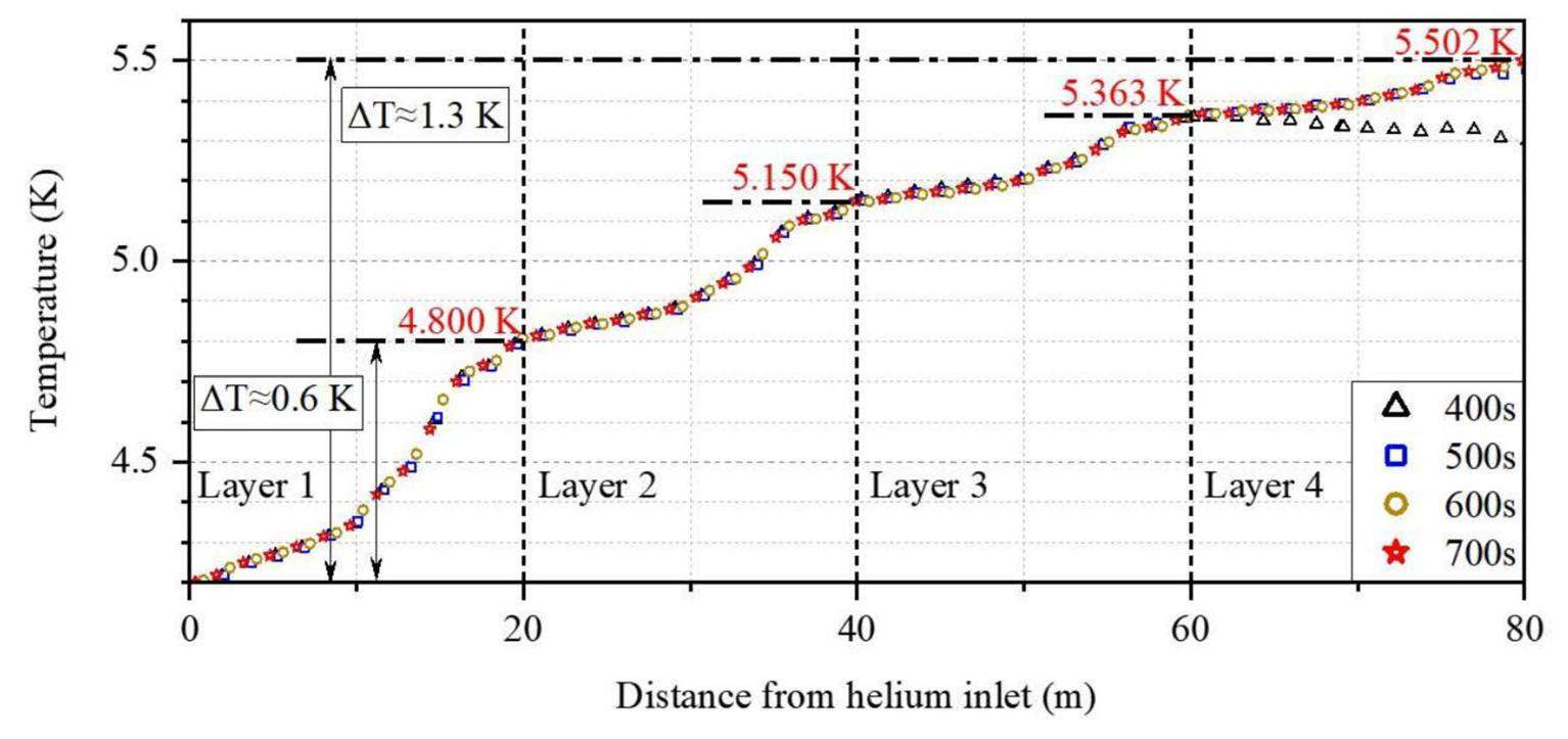
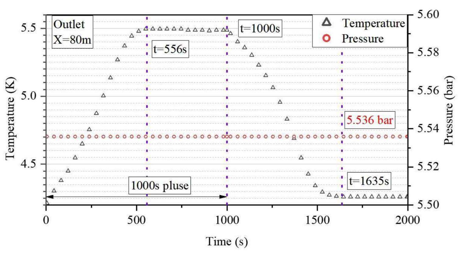
In the steady-state mode, both nuclear heating and heat transferred from the case to the coil were considered. Figure 11 illustrates the temperature evolution of the superconducting strand. The temperature history at the helium-flow outlet and pressure decrease are shown in Fig. 12. The conductor-load temperature sequentially increased with distance from the helium inlet owing to the heat load, and the average temperature continued to increase over time. By the end of the 1000 s plasma pulse, the conductor temperature at the end of the helium-flow channel reached 5.502 K, indicating an increase of 1.3 K from the initial value of 4.2 K. The most substantial temperature increase occurred in the first turn (0 m–20 m distance from the helium inlet) of HF-7, contributing approximately 45%–50% of the total temperature increase. A milder increase was observed in the last turn (60 m–80 m distance from the helium inlet). The conductor temperature at the helium outlet reached its peak at 550 s, started to decrease after 1000 s, and reached its minimum value after1550 s. The outlet pressure was 5.536 bar. The initial temperature margin under the aforementioned peak magnetic field and strain conditions was 3.0 K. After subtracting other heat loads apart from nuclear heating (such as hysteresis loss, coupling currents, thermal radiation, and conduction, which amount to approximately 0.45 K), a remaining temperature margin of 1.25 K was achieved, satisfying the design requirement of > 1.0 K.
Transient mode
In the transient mode, the nuclear heat directly absorbed by the conductor remained constant throughout the 10-s pulse. However, the heat transferred from the case was not included in the analysis. Unlike the extended plasma-pulse mode, where the conductor and coolant can approach a thermal-equilibrium state, the 10-splasma pulse prevents them from achieving such an equilibrium. Consequently, in this mode, the total heat load can be approximated as 4.5 times the nuclear heating load in the steady-state mode.
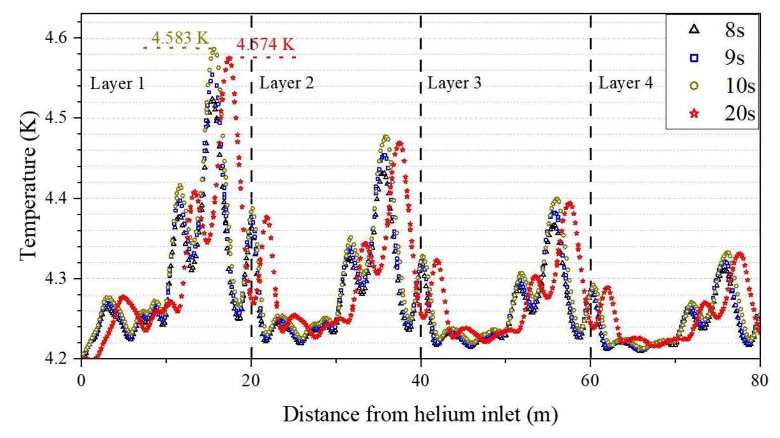
Figure 13 shows the temperature evolution of the superconducting strand over a 10-s pulse. In general, the conductor temperature followed an increasing trend that aligned with the nuclear-heating load. The first turn of HF-7, which experienced the greatest nuclear heating, exhibited the most significant temperature variation. At the end of the pulse, a peak temperature of 4.583 K was reached, indicating an increase in 0.38 K over the inlet temperature. After deducting the other thermal loads, the remaining temperature margin was approximately 2.17 K, which satisfied the design requirements. The outlet pressure was maintained at 5.536 bar. Compared with the steady-state mode, the transient mode afforded a larger temperature margin.
Discussion and summary
The proposed method effectively combines neutronics and thermal-hydraulic analyses, resulting in a comprehensive assessment of the effect of the heat load, magnetic field, and cooling conditions on TF coils. Compared with traditional methodologies, this improved method introduced two crucial advancements in neutron modeling and thermal-hydraulic analysis.
To demonstrate the application of this improved approach, an under-designed fusion reactor was used. During the neutronics-modeling phase, a parametric modeling technique was employed to construct a heterogeneous TF model. This not only reduced modeling time for model changes in the design-optimization process, but also enhanced the counting accuracy by more than 12%. Before carrying out a conductor-temperature analysis, the proposed method considers the cumulative effects of total heat load, magnetic field, and cooling conditions. Subsequently, one or two cooling circuits facing the most severe conditions were identified for the subsequent thermal-hydraulic calculations. This streamlined the workload for subsequent analyses.
Building on the aforementioned method, a more precise analysis of the thermal impact on TF temperature under the standard operational conditions of a fusion reactor can be achieved, thereby expediting the design process. Furthermore, this method offers pivotal insights for optimizing the structure and cooling arrangement of fusion superconducting magnet systems.
High temperature superconductors for fusion magnets
. Nucl. Fusion 58, 103001 (2018). https://doi.org/10.1088/1741-4326/aad835Concept design of hybrid superconducting magnet for CFETR Tokamak reactor
. 2013 IEEE 25th Symposium on Fusion Engineering (SOFE).Technology development and mass production of Nb3Sn conductors for ITER toroidal field coils in Japan
. Nucl. Fusion 51, 113015 (2011). https://doi.org/10.1088/0029-5515/51/11/113015European DEMO design strategy and consequences for materials
. Nucl. Fusion 57, 092002 (2017). https://doi.org/10.1088/1741-4326/57/9/092002Materials for future nuclear energy systems
. J. Nucl. Mater. 527, 151837 (2019). https://doi.org/10.1016/j.jnucmat.2019.151837The ITER magnet systems: progress on construction
. Nucl. Fusion 54, 013006 (2013). https://doi.org/10.1088/0029-5515/54/1/013006Neutronic analysis of the JT-60SA toroidal magnets
. Fusion Eng. Des. 84, 1947-1952 (2009). https://doi.org/10.1016/j.fusengdes.2009.01.035Thermal-hydraulic analysis of the CFETR TF coils when subject to nuclear heat load
. Fusion Eng. Des. 173, 112850 (2021). https://doi.org/10.1016/j.fusengdes.2021.112850Progress on neutronic analysis for CFETR
. Nucl. Fusion 62, 056011 (2022). https://doi.org/10.1088/1741-4326/ac3f1cFlexible heat resistant neutron shielding resin
. J. Nucl. Mater. 417, 850-853 (2011). https://doi.org/10.1016/j.jnucmat.2010.12.291The design, fabrication and properties of B4C/Al neutron absorbers
. J. Nucl. Mater. 437, 350-358 (2013). https://doi.org/10.1016/j.jnucmat.2013.02.050Advanced neutron shielding material using zirconium borohydride and zirconium hydride
. J. Nucl. Mater. 386, 119-121 (2009).Nuclear loads and nuclear shielding performance of EU DEMO divertor: A comparative neutronics evaluation of two interim design options
. Nucl. Mater. Energy 23, 100745 (2020). https://doi.org/10.1016/j.nme.2020.100745Thermal-Hydraulic Analysis of the Low-Tc Superconductor (LTS) Winding Pack Design Concepts for the DEMO Toroidal Field (TF) Coil
. IEEE T. Appl. Supercon. 26, 1-5 (2016). https://doi.org/10.1109/TASC.2016.2542003Progress in the conceptual design of the CFETR toroidal field coil with rectangular conductors
. Nucl. Fusion 60, 046032 (2020). https://doi.org/10.1088/1741-4326/ab742dNumerical simulation of the stability in long cable-in-conduit conductors for fusion magnets
. Fusion Technol. 21, 1914-1917 (1992). https://doi.org/10.13182/FST92-A29999Stability analysis of the ITER TF and CS conductors using the code Gandalf
. IEEE T. Appl. Supercon. 9, 612-615 (1999). https://doi.org/10.1109/77.783370Stability analysis of the ITER TF conductor
. AIP Conference Proceedings.Design of the JT-60SA superconducting toroidal field magnet
. IEEE T. Appl. Supercon. 20, 572-575 (2010). https://doi.org/10.1109/TASC.2010.2041335Impact of plasma disruption on magnetic field variations and heat deposition in the TF conductor of JT-60SA
. IEEE T. Appl. Supercon. 22, 4803005-4803005 (2010). https://doi.org/10.1109/TASC.2011.2182171Analysis of the thermal-hydraulic effects of a plasma disruption on the DTT TF magnets
. IEEE T. Appl. Supercon. 32, 1-7 (2022). https://doi.org/10.1109/TASC.2022.3166869Design updates and analysis of the Korean fusion demonstration reactor superconducting toroidal field magnet system
. Fusion Eng. Des. 155, 111587 (2020). https://doi.org/10.1016/j.fusengdes.2020.111587A preliminary conceptual design study for Korean fusion Demo Reactor magnets
. Fusion Eng. Des. 88, 488-491 (2013). https://doi.org/10.1016/j.fusengdes.2013.02.123Thermal, Electromagnetic and Structural Performance Evaluation of CFETR Toroidal Field Superconducting Magnet
.Conceptual design of the CFETR toroidal field superconducting coils
. IEEE T. Appl. Supercon. 25, 1-9 (2015). https://doi.org/10.1109/TASC.2015.2396942JT-60SA toroidal field magnet system
. IEEE T. Appl. Supercon. 18, 505-508 (2018). https://doi.org/10.1109/TASC.2008.920827Analysis of the effects of the nuclear heat load on the ITER TF magnets temperature margin
. IEEE T. Appl. Supercon. 24, 1-4 (2013). https://doi.org/10.1109/TASC.2013.2280720Thermo-hydraulic analyses associated with a CEA design proposal for a DEMO TF conductor
. Cryogenics 80, 317-324 (2016). https://doi.org/10.1016/j.cryogenics.2016.05.004Neutronic design studies of a conceptual DCLL fusion reactor for DEMO and commercial power plants
. Nucl. Fusion 56, 016001 (2015). https://doi.org/10.1088/0029-5515/56/1/016001ENDF/B-VIII. 0: 8th major release of the nuclear reaction data library with CIELO-project cross sections, new standards, and thermal scattering data
. Nucl. Data Sheets 148, 1-142 (2018). https://doi.org/10.1016/j.nds.2018.02.001The joint evaluated fission and fusion nuclear data library, JEFF-3.3
. The Eur. Phys. J. A. 56, 181 (2020). https://doi.org/10.1140/epja/s10050-020-00141-9Mechanical properties evaluation of ReBCO CICC jacket based on super-austenitic stainless steel for CFETR high-field magnet
. Nucl. Mater. Energy 34, 101344 (2023). https://doi.org/10.1016/j.nme.2022.101344Scaling law for the strain dependence of the critical current in an advanced ITER Nb3Sn strand
. Supercond. Sci. Tech. 20, 186 (2007). https://doi.org/10.1088/0953-2048/20/3/013MCNP–A General Purpose Monte Carlo N-Particle Transport Code. version 5
. (Technical Report LA-UR-03 1987;Tokamak DT neutron source models for different plasma physics confinement modes
. Fusion Eng. Des. 87, 787-792 (2012). https://doi.org/10.1016/j.fusengdes.2012.02.025Optimization of the cooling design of TF coil case on CFETR
. Fusion Eng. Des. 172, 112922 (2021). https://doi.org/10.1016/j.fusengdes.2021.112922Numerical model for the simulation of quench in the ITER magnets
. J. Comput. Phys. 125, 26-41 (1996). https://doi.org/10.1006/jcph.1996.0077Evaluation of the ITER cable in conduit conductor heat transfer
. Proceedings of the Twentieth International Cryogenic Engineering Conference (ICEC20).The authors declare that they have no competing interests.

