Introduction
The sPHENIX experiment at the Relativistic Heavy Ion Collider (RHIC) aims to conduct fundamental studies of both hot and cold quantum chromodynamic (QCD) matter properties through the measurement of jets, heavy flavor mesons, quarkonia, and other rare processes originating from hard scattering [1-3]. These hard probes of different energy scales will allow us to map out details of the parton structure of the nucleons and the dynamic evolution of the strongly interacting Quark-Gluon Plasma (QGP).
In addition to QCD physics at high temperatures and energy densities, sPHENIX will explore proton spin, transverse momentum-dependent parton distribution functions, and cold nuclear effects[4, 5]. Based on a substantial amount of 141 billion Au+Au events, sPHENIX is expected to provide stringent constraints on jet observables and the coupling of b-quarks to the QGP medium through RAA measurements, extending to the low-pT region. RAA denotes the nuclear modification factor, where the deviation from unity indicates nuclear medium effects [6]. In addition, Υ studies will be performed with a clear differentiation between
The sPHENIX detector is a cylindrical detector that uses a solenoidal magnet previously used in the BaBar experiment, which covers the pseudo-rapidity
From November 2019 to December 2021, the Chinese sPHENIX groups (Fudan University, Peking University, and China Institute of Atomic Energy) produced 1248 EMCal module blocks (20% of the EMCal system) for the sPHENIX experiment. These blocks covered the high η region (
EMCal module fabrication
EMCal block
To increase the electron identification efficiency and hadron rejection power and minimize the overall size, sPHENIX requires a compact EMCal detector with a small Molière radius and short radiation length with high energy resolution. The tungsten powder/scintillating fiber (W/ScFi) EMCal technology was initially developed by the University of California, Los Angeles EMCal research group and was adopted for the R & D module [12]. The W/ScFi EMCal has a geometrical configuration similar to the "Spaghetti" calorimeter (SPACAL) design that has been used in previous experiments [13, 14]. A single EMCal block consisted of scintillating fibers running longitudinally (Z) supported by six copper screens embedded in an absorber made of tungsten powder infused with epoxy. Photons from the scintillating fibers were collected at one end and read using Silicon PhotoMultipliers (SiPMs) coupled with four light guides. The choice of SiPM is largely based on its compactness and performance in a strong magnetic field. The material density of the W/ScFi blocks is expected to be 9 g/cm3~10g/cm3.
One of the major considerations in the EMCal detector design is optimizing the efficiency of electron identification. For Υ particle measurement, it is necessary to reject the hadron background by utilizing the correlation between the track momentum and the energy measured in EMCal. Hadrons misidentified as electrons contribute to the combinatorial background of the Υ-invariant mass spectrum. Meanwhile, the Electromagnetic Calorimeter must have a radius smaller than 140 cm to be compact enough to fit the magnet system[2].
According to the sPHENIX physics goal and geometrical requirements of the detector, the EMCal detector should exhibit a high degree of segmentation with a small dead area for precise jet and Υ measurements. The EMCal block design was based on the W/ScFi detector technology. We used tungsten powder as the stopping material and a scintillating fiber as the active sampling component. Simulations and prototype beam tests were conducted using Fermilab. A linear response and impressive energy resolution of
EMCal segmentation and resolution are major physical requirements. In heavy-ion collision experiments, a small Molière radius and fine segmentation are necessary to measure the electromagnetic cluster energy with minimum overlap from the potential background. Each calorimeter block was assembled into towers of size Δη × Δϕ = 0.024 × 0.024 using 2 × 2 light guides at the readout end. The physical size of each tower was slightly larger than the Molière radius of 2.3 mm. Each block comprises 2668 fibers and is molded with a tungsten powder/epoxy mixture. The cylindrical barrel consisted of 64 sectors distributed uniformly in the azimuth. Each sector has 24 blocks along the beamline, and each row has four blocks along the ϕ-direction. The layout is illustrated in Figure 1 of [16, 15].
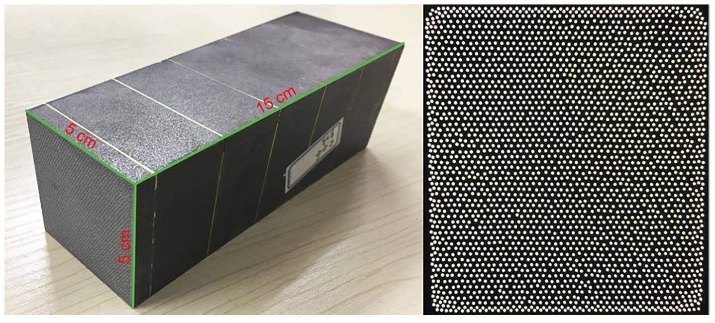
Figure 1 presents an image of the fabricated EMCal block from the Chinese sPHENIX group. Scintillating fibers with a diameter of 0.47 ± 0.01 mm were embedded uniformly in the block with an approximate 1.0 mm 2-D distance between the fibers. The fibers were fixed in positions using six copper screens before molding, and the tungsten powder was conjuncted with epoxy. The key characteristics of the sPHENIX EMCal Block are listed in Table 1.
| Parameter | Value |
|---|---|
| Block size (cm3) | ~5×~5×~15 |
| Segmentation, Δη × Δϕ | 0.024 × 0.024 |
| Absorber | Tungsten |
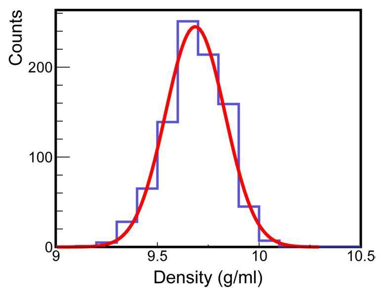
| Average density (g/cm3) | 9.68 |
| Average mass (kg) | 3.54 |
| Radiation length, X0 (mm) | 7 |
| Molière radius (cm) | 2.3 |
| Fiber type | Saint-Gobain BCF12-SC |
| Kuraray SCSF-78 | |
| Fiber diameter (mm) | 0.47 |
| Fiber number | 2668 |
| Fiber spacing (mm) | 1.0 |
| Average sampling fraction | 2.1% |
| Energy resolution (σE / E) |
The sPHENIX EMCal blocks were arranged in a projective geometry such that the blocks pointed toward the center of the beam interaction region within the sPHENIX detector. Six types of block configurations were designed depending on the longitudinal position. The blocks fabricated and studied in this work were for the high-η region (
Tungsten Powder and Scintillating Fibers
The selection of tungsten as an energy-absorbing material is based on its higher stopping power (dE/dx) compared to other possible material choices, allowing compactness for the EMCal design. With the abovementioned radiation length X0 being 7 mm and Molière radius of 2.3 mm, the superior stopping power of tungsten enables high-efficiency absorption and measurement of incoming particle energies. In the W/ScFi block, the scintillating fibers were oriented in a longitudinal direction. When charged particles generated by electromagnetic showers from photons or electrons interact with the scintillating fibers, they ionize and excite atoms and molecules within the fibers, emitting scintillation light during de-excitation. The emitted light is then detected by a SiPM coupled with a light guide and converted into electron-hole pairs, which electronics can read out. Thus, similar to the SPACAL calorimeter design, W/ScFi EMCal also has a sub-nanosecond timing resolution. The diameter of the scintillating fibers and the space between the fibers are related to the EMCal sampling fraction, which reaches approximately 2.1%. These were optimized based on simulation studies to obtain the desired performance [12].
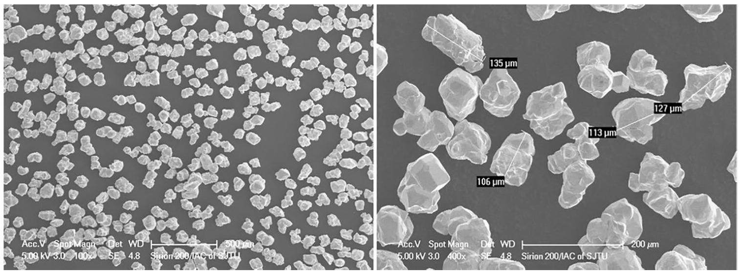
The compactness of the EMCal block and the minimal disturbance of the magnetic field requires the tungsten powder to have a high density and high purity. The ferromagnetic contamination in the tungsten powder should be below 100 ppm. Meanwhile, the granulation of the tungsten powder should aim to maximize the block density and optimize the fluidity of the epoxy in the tungsten powder. To meet these requirements, we systematically sampled and characterized the tungsten powder. Figure 2 shows scanning electron microscopy (SEM) images of the tungsten powder used in the block fabrication. These tungsten powders have good shape uniformity, with a typical size of approximately 100 μm, enabling high-density and smooth epoxy infusion during block casting.
We sampled 200 g from 1/5 of the entire batch of procured tungsten powder to measure the compacted powder density. The tungsten powder was poured into a cylindrical container, and a vibration table was used to minimize the gaps between the powder grains. We then measured the powder volume in a cylindrical container and calculated the density. The density of the powder ranged from 11.20 g/cm3 ∼ 11.77 g/cm3, with an average density 11.51 g/cm3.
To minimize the possible influence of the magnetic field on block performance, we required the material’s contents of iron, cobalt, and nickel to be as low as possible. For material selection, we measured the isotope content of the samples using inductively coupled plasma mass spectrometry (ICP-MS). Hydrofluoric acid and nitric acid were used to dissolve the materials. Because hydrofluoric acid corrodes the glass material, a platinum-based setup was designed for this test.
A test sample with 4.01392 g tungsten powder, 10 ml 26% HNO3, and 9 ml 30% HF was prepared and diluted 300 times for the measurement. The analysis results, including the statistical uncertainties, are presented in detail in Table 2. The table shows ferromagnetic contamination is below 100 ppm, which meets the design requirements, whereas the nonferromagnetic elements are negligible for the detector performance.
| Element | Content (ppm, wt) | Statistical uncertainty |
|---|---|---|
| Fe | 0.00164 | ± 0.00040 |
| Co | 1.72 | ± 0.14 |
| Ni | 0.0124 | ± 0.0007 |
| Zn | 0.0207 | ± 0.0024 |
| Rb | 0.0022 | ± 0.0004 |
| Cs | 0.0077 | ± 0.0006 |
| Tl | 0.317 | ± 0.016 |
| Pb | 0.161 | ± 0.012 |
Plastic scintillating fibers used for block production have been well evaluated and selected based on their material properties and physical characteristics. The core material is polystyrene (PS) with poly (methyl methacrylate). In terms of the optical properties, the scintillating fiber has an emission spectrum that peaks at 450 nm with a decay time of 2.8 ns for the scintillation light signal. Notably, a fiber with an attenuation length greater than 4.0 m can effectively transmit light over a considerable distance with a small loss, which is well-suited for the EMCal block R&D[18].
Mold Design
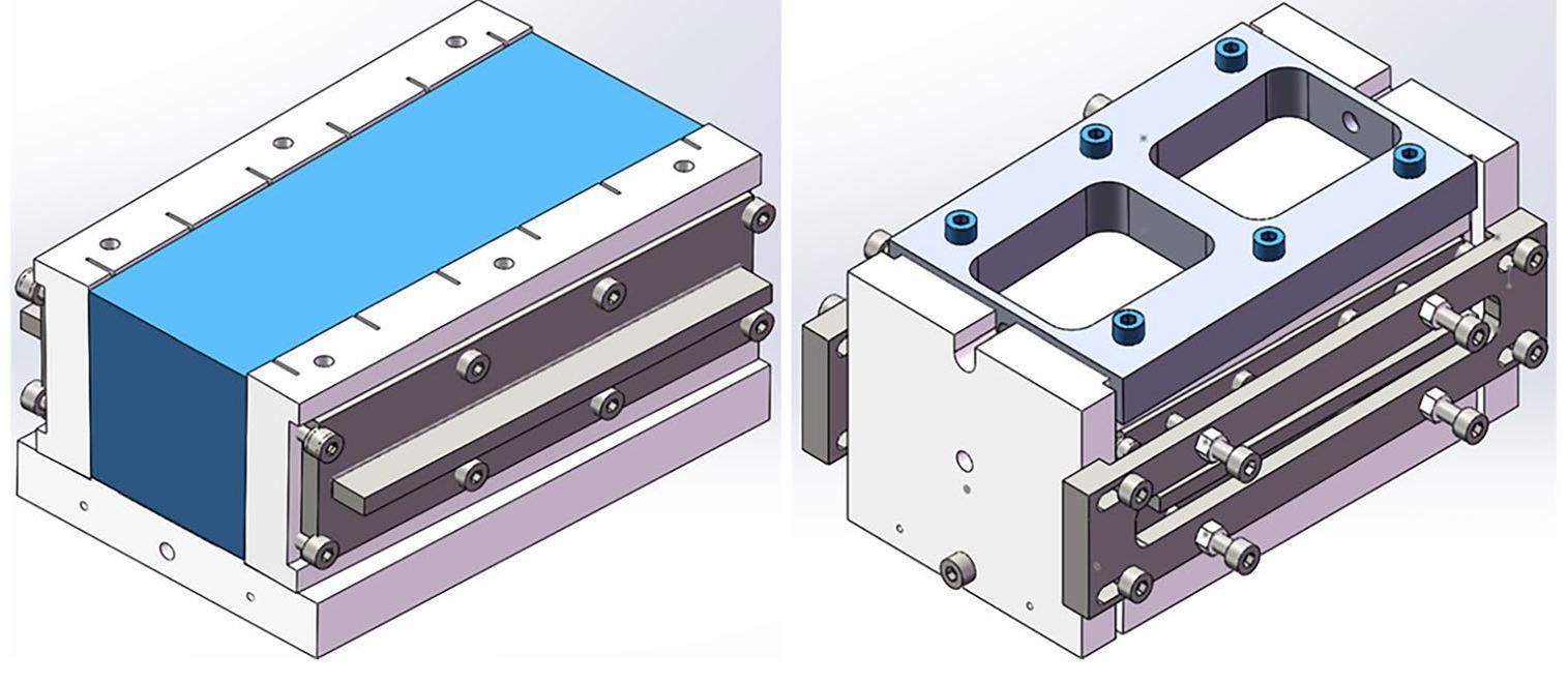
The mold used to produce the EMCal blocks consisted of six plates made of Delrin® Polyformaldehyde (POM) resin. Delrin® Polyformaldehyde (POM) has the advantage of not adhering to the epoxy, which is optimal for demolding. However, it has the drawback of limited rigidity, which makes it easily deformed during mold machining. The side plate tended to bend inward after processing the slots on the inside face to position the screens. This deformation leads to significant changes in the dimensions and shapes of the blocks compared to the initial design requirements. To satisfy these geometrical requirements, we explored various methods for enhancing the rigidity of the side plate. As shown in Fig. 3, two additional plates were designed. The reinforcing plate prevents the otherwise inevitable bending of the side plate, while the clamping plate ensures that all the plates are in the correct positions and that all the dimensions are as close to the design goal as possible. The dimensions were highly dependent on the mold conformity during assembly. These optimizations reduce mold deformation during casting and ensure the uniformity of the blocks produced.
Production Procedure
The sPHENIX EMCal detector subsystem can be divided into block production, module assembly, and sector assembly. A schematic workflow of the primary block creation procedure is presented in Fig. 4.

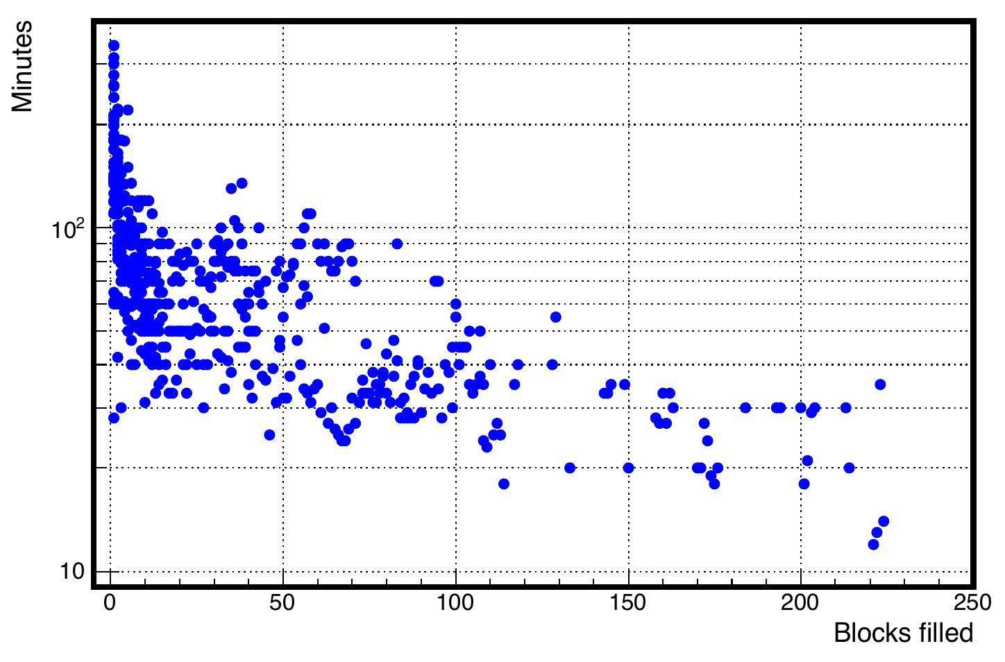
The fibers were cut into specific lengths and filled into a container passing through holes on six copper screens secured by a 3D-printed holder. It took more than two hours to complete the first few sets, while the time cost quickly decreased to approximately 15 min as the workers gained more experience after completing more sets. The fiber-filling times are summarized in Fig. 5. The fibers, along with the copper screens, were then assembled into a mold, as shown in the left plot of Fig. 6.
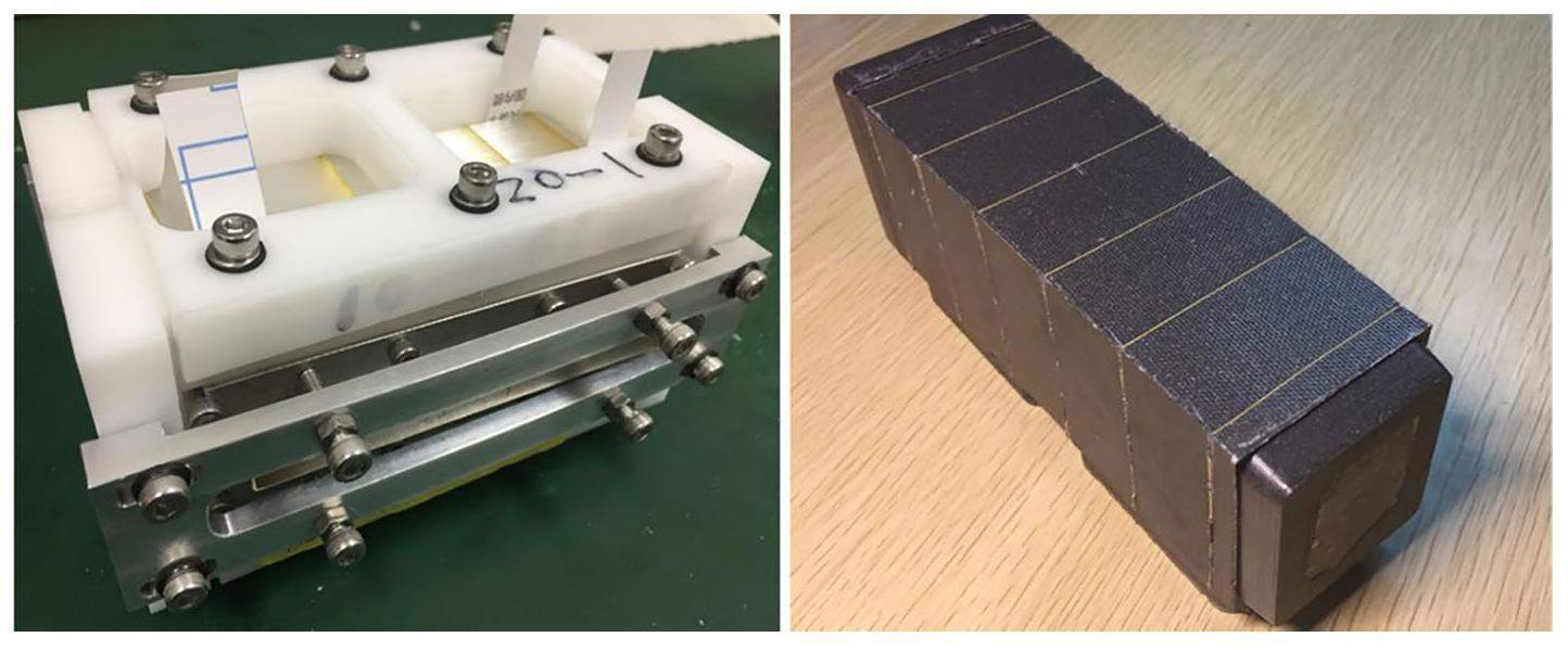
The mold was then filled with tungsten powder and sealed. A vibration platform was used to compact tungsten powder. Subsequently, the mold filled with tungsten powder was filled with epoxy and left for 24 h to cool and solidify. The epoxy used is EPO-TEK® 301 [19]. It consists of two components and has a pot life of about [range-phrase = –]12 hours. It was mixed at a temperature of 50 ℃ to increase the liquidity before being injected into a mold filled with tungsten powder. A negative-pressure environment was created inside the mold using a vacuum pump via ventilation holes placed on the bottom plate of the mold, which was proven to be helpful in ensuring that the epoxy flowed uniformly inside the block. The vacuum pump caused the epoxy to flow quickly to the bottom before solidifying.
After demolding the blocks (shown on the right-hand side of Fig. 6), the blocks are sent to the factory for machining. The cutting process, which involved trimming both ends of the block, posed the risk of tungsten powder debris covering the end faces of the scintillating fiber, leading to a loss of light transmission. To address this issue, specific procedures were employed during the machining process, including employing a hard diamond blade for coarse cutting at a gentle and appropriate speed and final cutting of minimal thickness to reduce the debris on the end faces of the fiber as much as possible. In addition, a luminous flux meter was used during block machining to identify blocks with low-light transmission for further processing.
Following the cutting process, comprehensive Quality Assurance (QA) studies were performed, including block dimension and density measurements, fiber quantity assessment through planar light transmission, scintillation light readout response tests, and cosmic ray tests. The cosmic ray test was performed by coupling four light guides to 16 Silicon PhotoMultipliers (SiPMs) in a readout setup. All QA procedures were designed to check block quality and evaluate deviations with respect to our design goals.
Block Quality Assurance and Testing
Block QA started with the materials used to make the blocks: tungsten powder and scintillation fibers. These materials were inspected to meet the requirements before use in block production. In this section, the QA procedures for each block of the production workflow are described.
Block Geometry and Density QA
For each block in the production workflow, the QA procedure included the measurement of the density, dimension, number of fibers, light flux, and basic scintillation properties. We set criteria to ensure that each block passed our pre-determined standards.
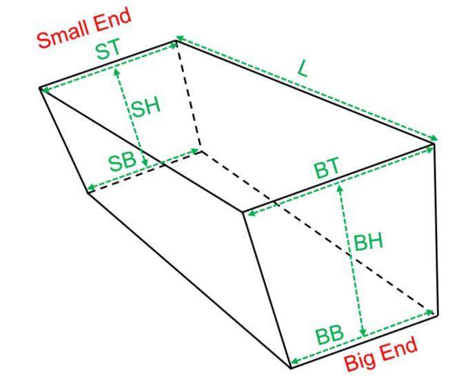
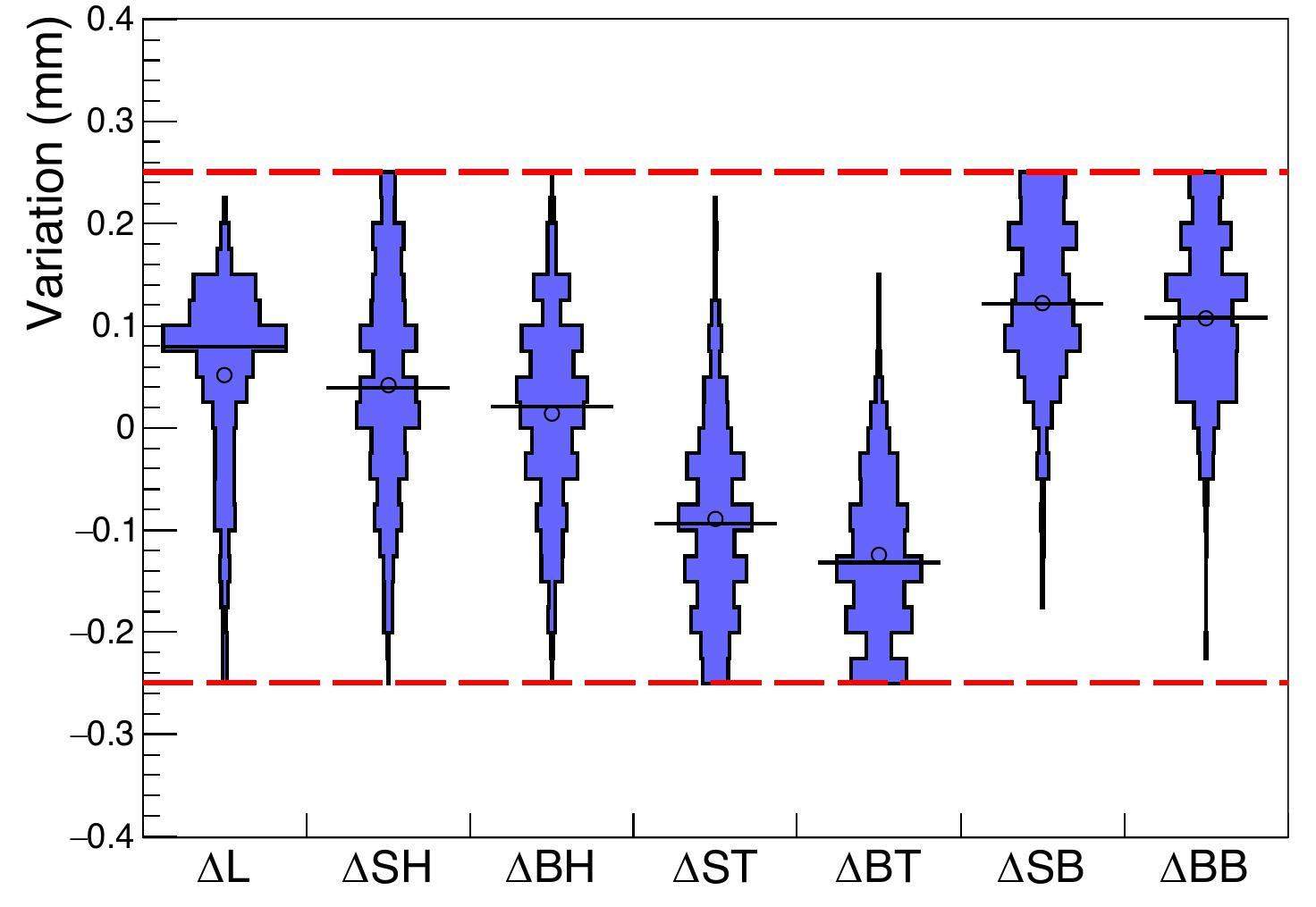
As shown in Fig. 7, each block is characterized by 7 dimensional parameters. The block length is denoted as L. B and S represent the big and small ends, respectively. At each end, the top (T), bottom (B), and height (H) were used to describe the surface. By combining the letters, we obtained L, SH, BH, ST, BT, SB and BB to characterize each block. The typical range for L is between 135 mm to 147 mm, whereas the other parameters are roughly between 45 mm to 55 mm. Precise measurement of these parameters allows for an accurate calculation of the total volume of each block. The ratio of the gross mass to the total volume provided the average density for each block. For most blocks, we achieved a tolerance of ± 0.25 mm in all dimensions, which is better than the initial goal 0.5 mm. Figure 8 shows the geometrical measurement results for the blocks within ± 0.25 mm tolerance. Note that for ΔST, ΔBT, ΔSB, and ΔBB, the deviation is higher than those for the other three. This could be because these dimensions are predominantly influenced by the mold rather than the machining process, making them difficult to control.
Within the specified tolerance, the volume of the block was calculated based on 3-dimensional measurement. Note that the geometrical shape of our block was a prismoid rather than a frustum. The volume is given by the equation
Fiber light transmission and scintillation property study
The light yield and light collection efficiency are important performance factors of EMCal. We expect 2668 fibers per block without loss of fibers. We counted the number of fibers of each block and calculated the fraction of the number of fibers as 2668. The plot on the right shows a typical image of the end of a block used to count the fibers. (Fig. 1) We discarded blocks with fiber fractions lower than 98%.
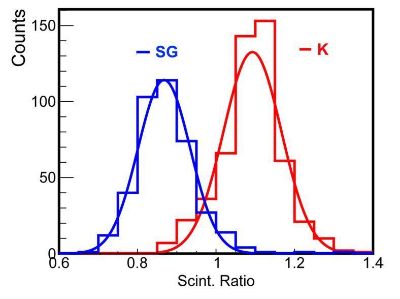
The scintillating light produced by the fiber was measured using five LEDs attached to one end of a block and a Photomultiplier Tube at the other end. The wavelength of the light source was selected as 367 nm to distinguish between the transmitted light and scintillation light (450 nm) in the block. This scintillation property study serves as a crucial evaluation of block quality. In addition, it provides useful data for comparing fibers from different providers. Figure 10 shows the relative scintillation light yield (as a reference) for blocks made with Kuraray fibers compared to blocks made with Saint-Gobain fibers. Our results indicated that the scintillation light yield of the Kuraray fibers was approximately 1.25 times higher than that of the Saint Gobain fibers. Despite this difference, both the fibers met the sPHENIX requirements for light production. Saint Gobain fibers were eventually selected to produce approximately 60% of the sPHENIX EMCal blocks. The small difference in the light yields of the two fibers was considered in the module calibration.
Cosmic Ray Test
We conducted tests using cosmic rays to investigate the light-yield properties of the EMCal blocks. When cosmic rays (mostly high-energy muons) pass through the block, the scintillating fibers along their path are excited, and the SiPM coupled to the small end of the block detects the scintillating light, as illustrated in Fig. 11. A reflector foil was placed at the large end of the block to reflect the light generated by the fibers.
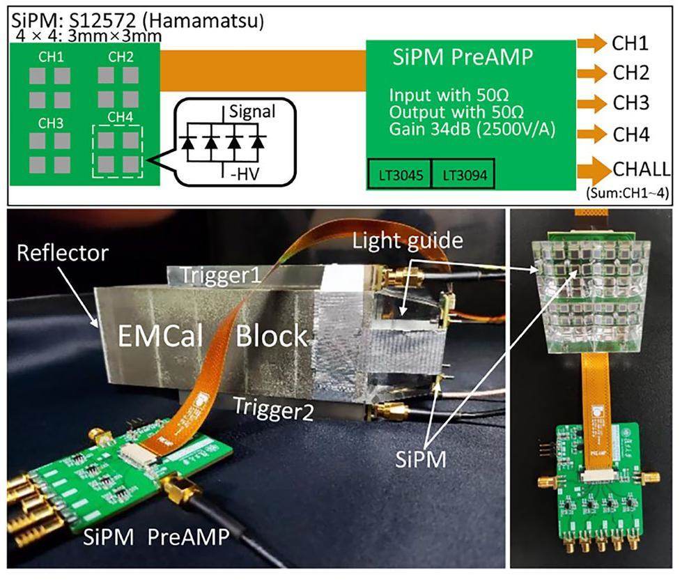
Initially, the cosmic-ray signals in the blocks were detected using a Photomultiplier Tube and compared with readouts from a plastic scintillator. We further modified the configuration of the blocks to make them compatible with the EMCal readout scheme in the sPHENIX experiment. Specifically, we used the S12572-015P SiPM from Hamamatsu [21]. Each block was segmented into four towers coupled to four light guides as the readout channels. Each light guide had four attached SiPMs, and each readout channel integrated the charge signals from these four SiPMs. The SiPM signal is sent to a pre-amplifier designed at Fudan University [22] to improve the signal-to-background ratio and then directed to a charge-to-digital converter (QDC) to obtain the energy spectrum.
Two Bismuth Germanate (BGO) crystals were placed at the top and bottom of the blocks as triggers. The signals were triggered when both were fired. The QDC was configured using a 200 ns window gate. We applied the same setup to all the blocks tested.
We present the QDC results for two types of blocks—one made with Kurary fibers, and the other made with Saint-Gobain fibers. The two blocks exhibited different scintillation properties, as shown in Fig. 10. The normalized cosmic-ray energy spectrum for each block exhibited two peaks, as shown in Fig. 12. The data points represent the test data, and the lines represent the fitting outline shape. The left peak is primarily attributed to the background induced by the false trigger from electronic noise and the environment, whereas the right peak corresponds to photons detected from cosmic rays.
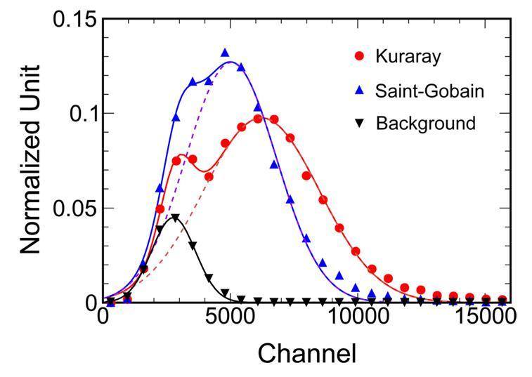
A double-peak Gaussian fit was applied to extract background data. The background spectrum was fitted with a Gaussian function, shown by the black line, and normalized to the fitted amplitude of the first peak of the block made of Kurary fibers. By subtracting the background, we quantitatively compared the responses of the different types of fibers to cosmic rays. The mean value for Saint-Gobain was 5028.2, whereas that for Kurary fiber was 6222.1, approximately 1.24 times higher than the former. The measured values are consistent with the scintillation results shown in Fig. 10.
Summary
The sPHENIX experiment deployed a novel barrel EMCal detector that uses recently developed tungsten powder/scintillating fiber detector technology. The EMCal design allowed for a very compact detector with high energy resolution and electron/hadron identification, meeting the performance requirements necessary for the scientific objectives of photons, jets and quarkonia measurements at RHIC.
R & D efforts were devoted to the production of the EMCal blocks in the high η region by the Chinese sPHENIX group. The tungsten powder was characterized and selected to ensure both high density and purity. Procedures for industrial-scale production of the EMCal blocks were established, and comprehensive QA studies were performed to ensure that each block produced met the pre-determined criteria. The QA procedures include measurements of the block’s geometrical dimensions, density, and scintillation properties.
The light produced by the blocks was tested using LEDs and cosmic rays. We compared the light yields of different types of fibers: Kuraray SCSF-78 and Saint-Gobain BCF-12. Our measurements indicated that Kuraray fibers produced approximately 1.25 times more light than the Saint-Gobain fibers for the same excitation source.
The novel tungsten powder/scintillating fiber detector technology demonstrated in this study is also a prospective calorimeter detector for future collider experiments, such as the Electron Ion Collider (EIC) [23] and the Electron-ion collider in China [24].
sPHENIX: An upgraded concept from PHENIX collaboration
. https://arxiv.org/abs/1207.6378[arXiv:1207.6378 [nucl-ex]].[PHENIX] An upgrade proposal from the PHENIX collaboration
. https://arxiv.org/abs/1501.06197[arXiv:1501.06197 [nucl-ex]].Hot QCD white paper: Exploring the phases of QCD at RHIC and the LHC
. https://arxiv.org/abs/1502.02730[arXiv:1502.02730 [nucl-ex]].Status and performance of sPHENIX experiment
. EPJ Web Conf. 276,Measurements of the lightest hypernucleus (HΛ3): progress and perspective
. Sci. Bull. 68, 3252 (2023). https://doi.org/10.1016/j.scib.2023.11.045.Suppression of hadrons with a large transverse momentum in central Au+Au collisions at sNN = 130-GeV
. Phys. Rev. Lett. 88,Charm hadron azimuthal angular correlations in Au + Au collisions at sNN=200 GeV from parton scattering
. Nucl. Sci. Tech. 30, 185 (2019). https://doi.org/10.1007/s41365-019-0706-z.Background reconstruction method for measuring the D-meson azimuthal angular correlations
Nucl. Sci. Tech. 32, 61 (2021). https://doi.org/10.1007/s41365-021-00896-w.Anisotropy flows in Pb-Pb collisions at LHC energies from parton scattering with a heavy quark trigger
. Nucl. Sci. Tech. 33, 15 (2022). https://doi.org/10.1007/s41365-022-00999-y.Overview and design of the sPHENIX TPC
. J. Phys. Conf. Ser. 1498,Technical design report for the ALICE inner tracking system upgrade
. J. Phys. G 41,Results of R&D for new construction technique for W/ScFi Calorimeters
. J. Phys. Conf. Ser. 404,A tungsten/scintillating fiber electromagnetic calorimeter prototype for a high-rate muon (g-2) experiment
. Nucl. Instrum. Meth. A 602, 396-402, (2009). https://doi.org/10.1016/j.nima.2009.01.007Development of forward calorimeter system for STAR experiments
. J. Phys. Conf. Ser. 587,Design and beam test results for sPHENIX electromagnetic and hadronic calorimeter prototypes
. IEEE Trans. Nucl. Sci. 65, 2901-2919 (2018). https://doi.org/10.1109/TNS.2018.2879047Design and beam test results for 2-D projective sPHENIX electromagnetic calorimeter prototypes
. IEEE Trans. Nucl. Sci. 68, 173-181 (2021). https://doi.org/10.1109/TNS.2020.3034643EPO-TEK® 301 Technical Data Sheet
. https://www.epotek.com/docs/en/Datasheet/301.pdf; [accessedSaint-Gobain Crystals
. https://luxiumsolutions.com/; [accessedHamamatsu Photonics
. https://www.hamamatsu.com; [accessedDesign and performance of high-speed, low-noise preamplifier for SiPM
. Nucl. Sci. Tech. 34, 169 (2023). https://doi.org/10.1007/s41365-023-01328-7, [ChinaXiv:202305.00148V2]A high luminosity probe of the partonic the substructures of the nucleons and nuclei
. https://digital.library.unt.edu/ark:/67531/metadc738811/; [accessedElectron ion collider in China
. Nucl. Tech. 43,Jin-Hui Chen and Huan-Zhong Huang are editorial board members for Nuclear Science and Techniques and was not involved in the editorial review, or the decision to publish this article. All authors declare that there are no competing interests.


