Introduction
As the first antiparticle discovered by humans, positrons have been widely used in both basic and applied research. For example, positron beams with 1010 e+/s high beam intensity and GeV energy are often employed as injection beams in large collider facilities [1]. Positron beams also play an important role in material performance testing combined with Positron Annihilation Lifetime Spectroscopy (PALS) [2-6] and Coincidence Doppler Broadening Spectroscopy (CDBS) [7-9], among other technologies. Currently, there are four methods for obtaining positron beams: 1) 22Na isotope source, isotope decay according to the reaction 22Na→22Ne+β+=νe [10, 11]; 2) Positrons generated through an electromagnetic cascade-shower process, where a heavy metal target is irradiated by high-energy electrons from an accelerator, such as LINAC [12-14]; 3) A heavy metal target irradiated by high-energy gamma-rays, called gamma-ray-driven positron source [15]; and 4) positrons generated by direct laser solid irradiation using an ultrahigh-power laser system, which has an ultrashort ps time structure [16, 17].
When determining the structural properties of materials using the positron Non-destructive Testing (NDT) method, the main requirements of the positron beam are as follows: 1) the positron energy must be adjustable to examine samples with different material densities and depths; 2) a high positron beam intensity is required for low detector efficiency; and 3) a positron beam spot must be selected to cover different sample sizes. Fortunately, a γ-ray-driven positron source based on a Laser Compton Scattering (LCS) gamma source meets all the above requirements, making it a good alternative for positron NDT [18].
The LCS gamma source, which was first operated in the 1970s, has the advantages of adjustable energy, quasi-monochromatic energy, adjustable flux, and a beam spot. With the gamma-ray-driven method, the positron beam generated based on the LCS gamma source has the corresponding characteristics of adjustable energy, high beam intensity, and a selectable beam spot. Because of these advantages, several renowned LCS gamma source facilities have been used for positron beam generation and application studies. The NewSUBARU BL01 LCS gamma source was used in a validation study of positron sources in 2019, and a positron beam with an intensity of 103 e+/s was observed based on 16.9 MeV and 8.5×10⁶ photons/s LCS gamma beams bombarding a lead target [19-21]. The UVSOR-III BL1U LCS gamma source also conducted a positron beam generation study using a γ-ray energy of approximately 6.6 MeV directly injected into a thick lead target, and a positron annihilation event rate of approximately 0.54 cps was measured [22]. Positron beam research is also planned for the ELI-NP LCS gamma branch (VEGA), which is still under construction in Romania [23-25].
The newly SLEGS LCS gamma source [26-30] at the Shanghai Synchrotron Radiation Facility (SSRF) has been available for users since 2023, and is the first LCS gamma source user device with a slant scattering collision mode. According to the characteristics of the SLEGS' γ-ray beam [31, 32], a positron beam is planned for construction and conduct Positron Annihilation Spectrum (PAS) research. A new positron beam with energy adjustability, high beam intensity, and a selectable positron beam spot is currently under discussion.
In this paper, we provide a detailed description of the design, simulation, and development of this new positron system. In Sec. 2, we briefly describe the SLEGS beamline and the parameters that must be considered. In Sec. 3, we describe the positron-generation system design. Sec. 4 presents the simulation details. Sec. 5 describes the development status. Finally, Sec. 6 concludes the paper.
SLEGS beamline and its parameters
SLEGS is one of the new beamlines of the SSRF Project II (2016–2024) [33, 34]. SSRF is a third-generation synchrotron radiation facility with a 3.5 GeV Stokes ring. The SSRF storage ring has two operating modes: top-up and single-bunch. When SSRF runs in top-up mode, four sets of electron trains in the storage ring, each with 125 consecutive bunches, are evenly spread in the 720 buckets [35]. When the SSRF runs in single-bunch mode, there is only one massive bunch in the storage ring [36].
Using a 10640 nm continuous CO2 laser collision with 3.5 GeV electron in the SSRF storage ring, SLEGS produces MeV energy gamma-rays, which is the first LCS gamma source obtained by changing the collision angle between the laser and electron to obtain adjustable gamma energy [37-39]. The electron and laser beam parameter characteristics in SLEGS are listed in Table 1. The commissioning results show that the SLEGS gamma-ray energy range reaches 0.66-21.7 MeV (the Compton scattering maximum energy of the scattered gamma-ray spectrum). The gamma-ray bandwidth exceeds 2%, with a tunable aperture of the collimator system (a ϕ1 mm collimator was used to obtain a 17 MeV gamma ray with a laser-electron collision angle of 124°), and will reach much more than 1% using a new type CO2 laser in the near future. The flux reaches 4×10⁷ photons/s under a 5 W CO2 laser power and will reach nearly e8photons/s with a 100 W CO2 laser power in the future. The beam spot has an adjustable range of ϕ1-25 mm on the experimental target at a distance of approximately 40 m from the collision point. Particularly, the SLEGS gamma-ray beam has a time structure of less than 2 ps when the storage ring is operated in single-bunch mode.
| Electron beam | Energy (GeV) | 3.5 |
| Configuration | 2 ps a bunch | |
| Top-up mode current (mA) | 300 | |
| Emittance ϵx/ϵy (nm rad) | 4.2/0.042 | |
| Beam radius σx/σy (μm) | 138.3/6.12 | |
| CO2 Laser | Pulse width (μs) | 50-1000 |
| Repetition rates (kHz) | 1 | |
| Wavelength (nm) | 10640 | |
| CW power (W) | 5-100 | |
| Beam radius ω (mm) | 0.1-1 |
Positron generation system design
Positron generation system is one of the most important application subsystems of the SLEGS beamline. The overall configuration of this system is shown in Fig. 1. It consists of γ-ray driven section, positron generated target, magnet separation section and PALS experimental section.

Gamma driven section
As a gamma-ray driven positron beam, the properties of the gamma-ray will transmit to the radiated positron. For example, the energy and intensity of the driven gamma-ray will partly determine the radiated positron's energy and intensity. Further more, the bandwidth and time structure of the gamma-ray will directly determine the bandwidth and time structure of the generated positron [40]. To obtain a suitable gamma beam for positron generation, a gamma driven section is necessary. It is composed of a collimation and start signal subsection.
The collimation subsection consists of coarse and fine collimators which confines the emission angle of gamma-ray to less than 0.5 mrad along the beamline and adjusts the beam spot within 1-25 mm in diameter. Based on the SLEGS collimation subsection, continuous adjustment of both the gamma-ray bandwidth and gamma beam spot is achieved, meeting the requirement for generating high-quality positron beams. The details of the collimation subsection are given in reference [26].
The start signal is necessary for PALS with the order picosecond. The main part (BaF2) of the PALS has been designed to routinely operate with beam durations of hundreds of picoseconds. Because of the fast response of the entire system, increasing the positron beam duration of a high performance PALS will result in a decrease in resolution [41]. For higher resolution, it is preferable to have positron bunch duration that are significantly smaller than the timescales of interest, i.e., at least in the range of a few to tens of ps. In that case, the resolution of the system will be only limited by the detector response. This limitations can be overcome at SLEGS positron generation system if the SSRF run in single-bunch mode. SSRF single-bunch mode with 10 ps pulse length and less than 2-ps jitters, combined with the continuously CO2 laser, SLEGS can routinely generate high-intensity γ-ray pulse beams of 10-ps duration. Then positron bunch with a 10-ps duration can be obtained as the result of the electromagnetic cascade initiated by these gamma pulses as they propagate through a high Z (mass number) converter target.
Positron generation target and separation section
The setup of the positron generation target and separation section is shown in Fig. 2. All targets can move in/out of the beam direction by a control mechanism. An electromagnet with tunable magnetic field is set just behind the target. The generated positron and electron are separated to opposite directions, while the penetrated gamma-ray and scattering gamma-ray are not affected by the magnetic field and go forward along the beam direction.
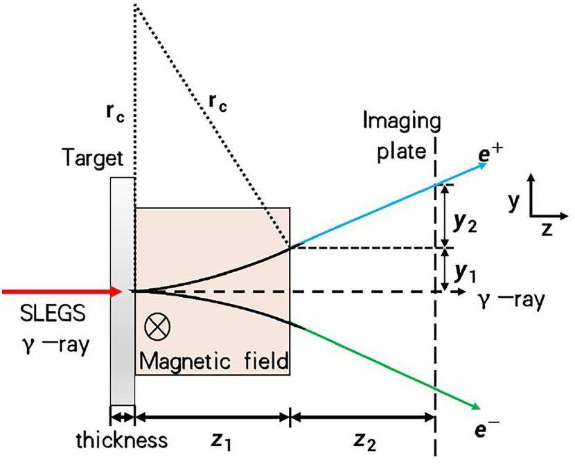
The detailed process of the free positron beam generated as follows. First, the gamma-ray beam irradiates a positron generating target. Second, the gamma-ray is converted in the target to a positron and electron pair in the Coulomb field of the target nucleus. Third, the generated positron and electron inherit the momentum of gamma-ray, together with the unreacted gamma-ray enter a square uniform strong magnetic field with the dimension of z1 for separating the positron and electron. The unreacted gamma-ray throughout to magnetic field along the z-axis, while the positron and electron separate from each other.
The separated free positron and electron will pass through a free flight distance of z2 then recorded by an imaging plate with the position in the vertical direction of y1, y2 and deflection radius rc, respectively. In order to obtain the positron beam with adjustable energy and flux, the magnetic field of the deflected electromagnet and the position z2 of the imaging plate which determines the positron flight distance are designed to have a certain adjustment range. Detailed parameters of the gamma driven section, generated target and separation section are listed in Table 2.
| Target | Material | Be/Cu/Pb |
| Purity (%) | 100% | |
| Diameter (mm) | 20 | |
| Thickness (mm) | 1.0–10.0 | |
| Electromagnet | Electromagnetic strength (Tesla) | 0.1–0.5 |
| Electromagnetic gap, z1 (mm) | 100 | |
| Field, length × width (mm2) | 100 × 100 | |
| Imaging plate | Size, length × width (mm2) | 400 × 400 |
| Position z2 (mm) | 0–600 |
GEANT4 Monte Carlo Simulation
The present simulation is based on the Geant4.10.04 version [42, 43] with the toolkit QGSP_BERT_HP which includes the G4EmStandardPhysics constructor describing electromagnetic process to determine the results of gamma transport and interaction. In the simulation, the LCS MeV energy γ-ray irradiates a high Z target producing positron beam. Based on the Monte Carlo simulation, systemic analysis of the target, magnetic field, and free flight distance have been carried out to achieve a high yield, adjustable energy, narrow bandwidth positron beam.
Typical gamma-ray and positron generation condition
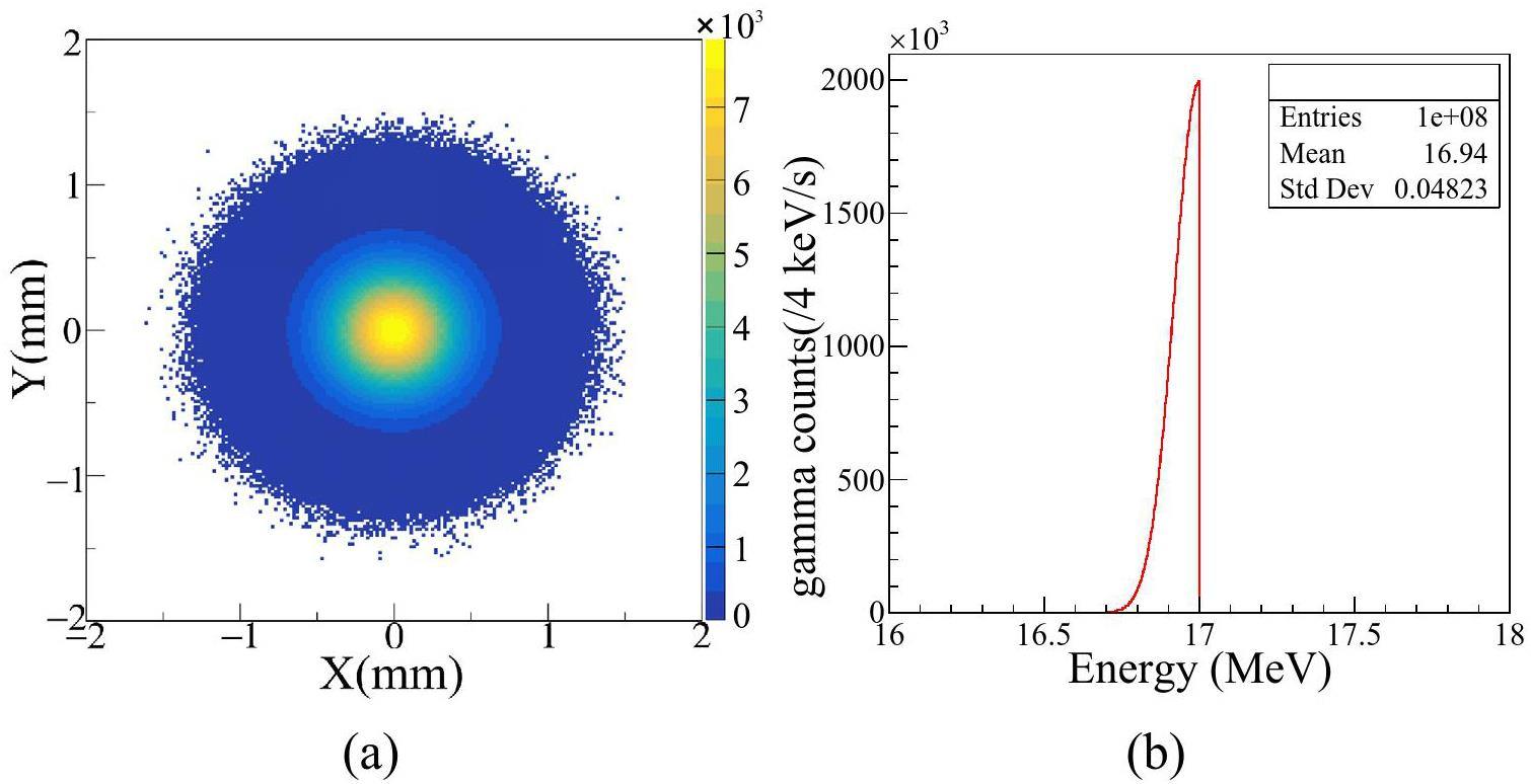
The gamma-ray with a quasi-monoenergetic energy of 17 MeV (0.5% bandwidth), flux of 108 photons/s, ϕ2(FWHM) spot size is performed in Fig. 3a and b. The reason for choosing this energy is that positron generation experiments at similar energies have been conducted in NewSUBARU BL01 [19, 44], also simulated with the EGS5 code, which can be used to verify the reliability of our simulation results.
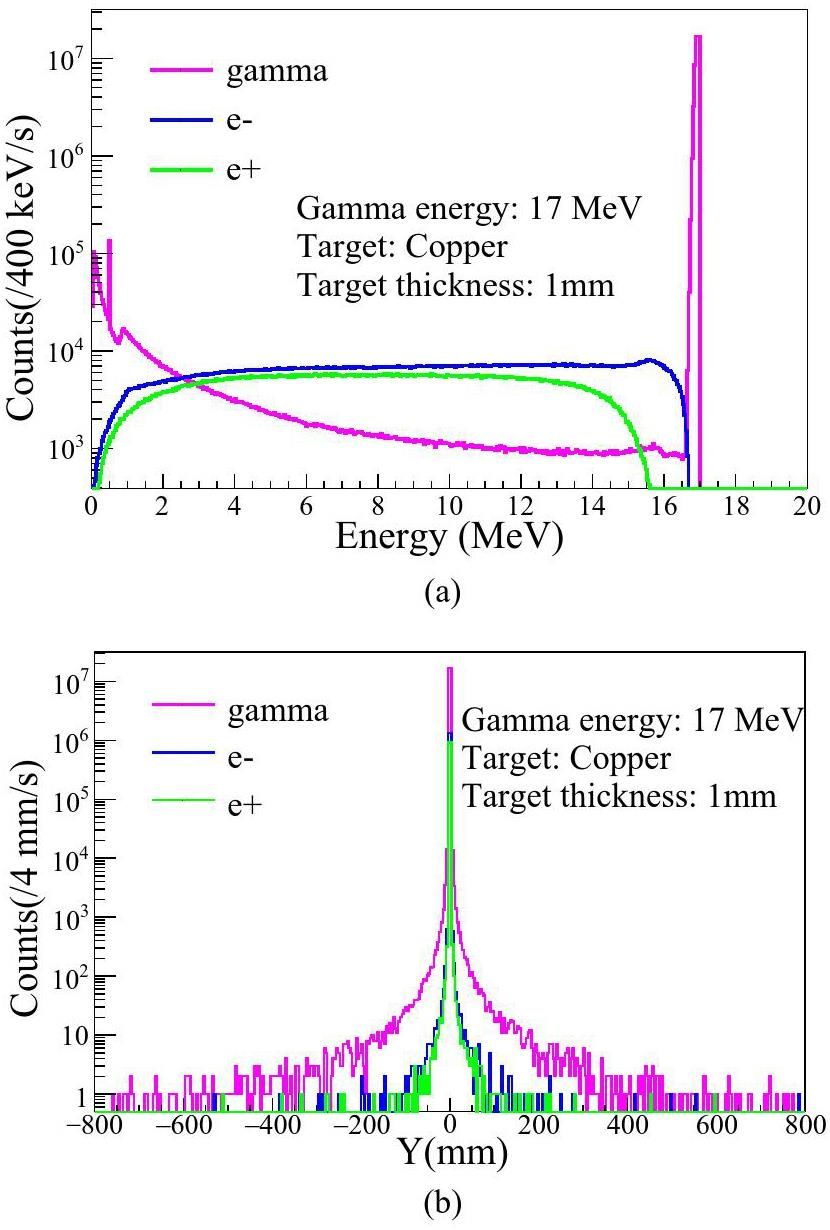
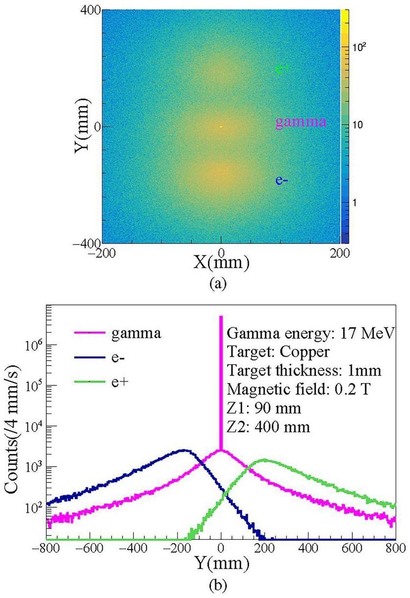
A general positron production process has been carefully analyzed to obtain an effective analysis method. The modulated 17 MeV gamma-ray irradiates a 1mm copper target, producing secondary particles, i.e. electron, positron and gamma-ray, the energy spectra are shown in Fig. 4a. Fig. 4b shows that the spatial distributions of the three particles are similar and overlapped when there is no electromagnetic separation section.
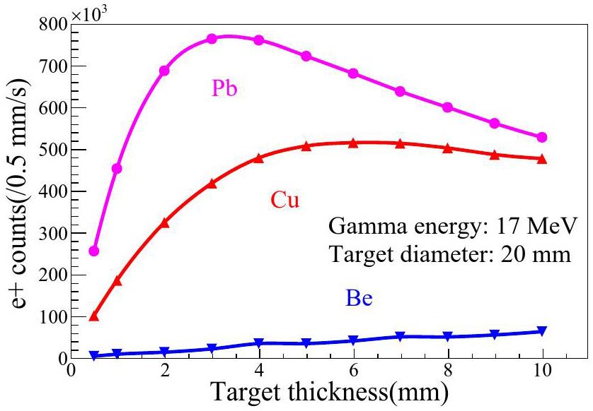
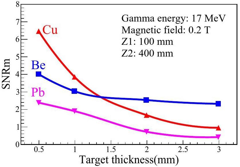
A yield of Beryllium (Be), Copper (Cu) and Lead (Pb) targets were calculated with the different thickness shown in Fig. 5. On the one hand, the high Z target is required to improve the yield of the electron pair effect, and on the other hand, the gamma background caused by the scattering of high Z materials, thus the optimized signal-to-noise ratio of positron should be considered with material.
We apply a constant magnetic field of 0.1–0.5 Tesla in the magnetic field area. Figure 6 shows that the magnetic field in the y direction separates the positron and electron. After passing through the magnetic field and transmitting a distance of 400 mm, the positron beam spot expands further to ϕ50 (in FWHM). The distribution of positron and electron is symmetrically separated along the y direction. The unreacted gamma is still distributed along the propagation direction, but secondary gamma will lead to more background.
In order to effectively reflect the quality of the generated positron beam, the Signal-to-Noise Ratio (SNR) parameter is employed. SNR is defined as the ratio of positron yield to background gamma yield at a certain measurement position, which is a complicated result of several factors, such as the position in y direction, incident gamma energy (E), target thickness (t), magnetic field (B), magnetic field range (z1) and Free Flight Distance(FFD) (z2). Then the SNR peak (written as SNRm) value, which is defined as the maximum of SNR, can reflect the optimized value of positron yield with a set of parameters (E, t, B, z1, z2). The SNR distribution, a function of y dirction, using the previous parameters (E: 17 MeV, t:1 mm, B: 0.2 T, z1: 100 mm, z2: 400 mm) is shown in Fig. 7.
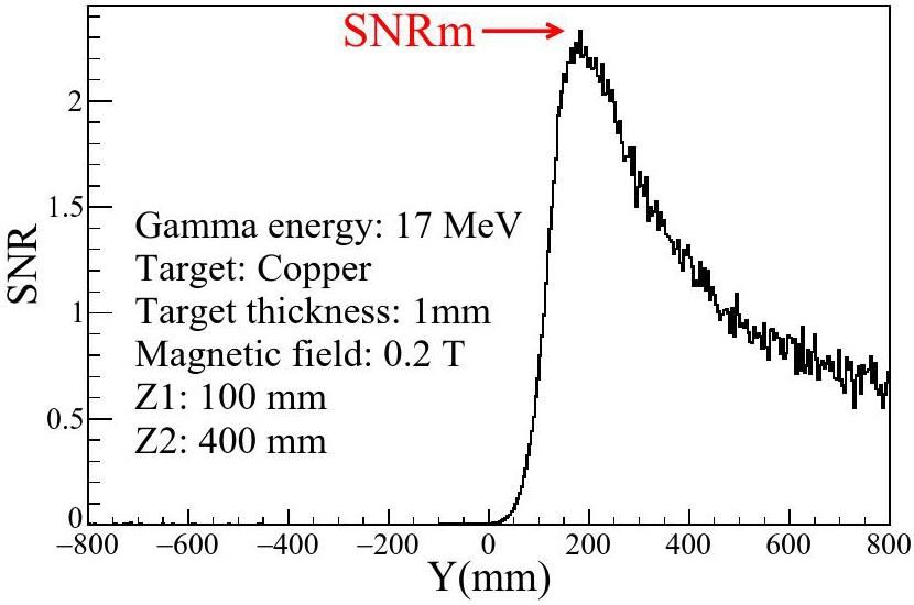
Figure 8 shows that judged by the SNRm, the optimized target thickness obtained by taking into account the contribution of gamma background is the 0.5–1.5 mm thickness copper target, while the lead target with the same thickness does not have the optimal signal-to-noise ratio because of the strong gamma scattering effect.
Determination of positron generation system parameters
Considering a practical positron generation process even further, in order to obtain a high quality positron beam with high flux, low background, narrow bandwidth, etc., a systematic consideration of target thickness, magnetic field size, magnetic field strength, and flight distance is required to be optimized for the positron beam.
Target
There are two main target parameters affecting the positron properties, the target material and its thickness. The positron yield gradually dominates as the Z value increases, but too large Z value will also lead to the secondary gamma background increase, which is detrimental the signal-to-noise of positron. If the target thickness is too small, the occurrence of the positron yield will decrease, while if thickness is too large, the scattered gamma background will increase significantly and the scattering of the positron in target will also lead to worse SNR. The positron spillover yield of whatever target materials decrease with the increasing target thickness.
Then generated positron passed through a 0.1–0.5 T magnetic field with variable length, the variation of SNRm of the three generated targets as a function of the target thickness have been shown in Fig. 8. It can be seen that the SNRm decreases as the thickness of the target increases. In the thin target region, less than 1.3 mm, the Cu target has the largest SNRm while Pb has the smallest SNRm. In the thick target region, larger than 1.3 mm, the Be has the highest SNRm and the Pb still has the lowest SNRm. The SNRm of the Be and Cu cross at 1.3 mm. Combined with the yield and SNRm, the 1 mm thickness Cu is finally chosen as the positron generating target at the parameters (E: 17 MeV, B: 0.2 T, z1: 100 mm, z2: 400 mm).
Magnetic field
The magnetic field also has two characteristic parameters, the field range (z1) and the magnetic induction intensity (B), which need to be considered together. Figure 9a shows a small area with high magnetic induction intensity has a similar effect to a large area with low magnetic induction intensity. At the same time, too high magnetic induction intensity will cause positron to move in a circular motion within the magnetic field and can't reach the receiver plate. While too low magnetic induction intensity will cause the deflection distance(y1) too small and the positron will still be mixed with the scattered gamma background, which will not be improved SNR.
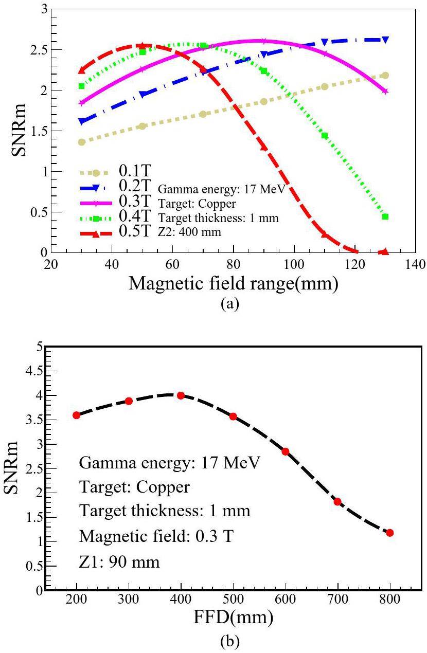
As shown in Fig. 9a, a wider magnetic field range(i.e., the z1 value in Fig. 2 is required for weak magnetic strengths of 0.1 T and 0.2 T. On the contrary, a small magnetic field area is enough for strong magnetic strengths of 0.4 T and 0.5 T. A maximum SNRm value appears at 90–100 mm magnetic field range (z1) under 0.3 T. Finally, the parameters of the magnetic field are taken as 0.3 T and 90 mm (E: 17 MeV, t: 1 mm, B:0.3 T, z1: 90 mm).
Free Flight Distance (FFD)
The free flight distance is the projection length of the transmitting path of the positron on the z-axis after passing through the magnetic field. After gaining deflection momentum in the magnetic field, the positron transmits out of the magnetic field region and continues to transmit in the y-axis direction in the free flight region. Since the positron energy distribution has a certain width, the deflection in the magnetic field will lead to further divergence of the positron beam spot, and the free flight distance should not be too large to obtain a suitable positron SNR and beam spot size. We also use SNRm to characterize the quality of positron beam after passing through different free flight regions, and it can be seen from Fig. 9b that the SNRm reaches its maximum at a free flight distance of 400 mm (E: 17 MeV, t: 1 mm, B: 0.3 T, z1: 90 mm, z2: 400 mm).
Beam qualities
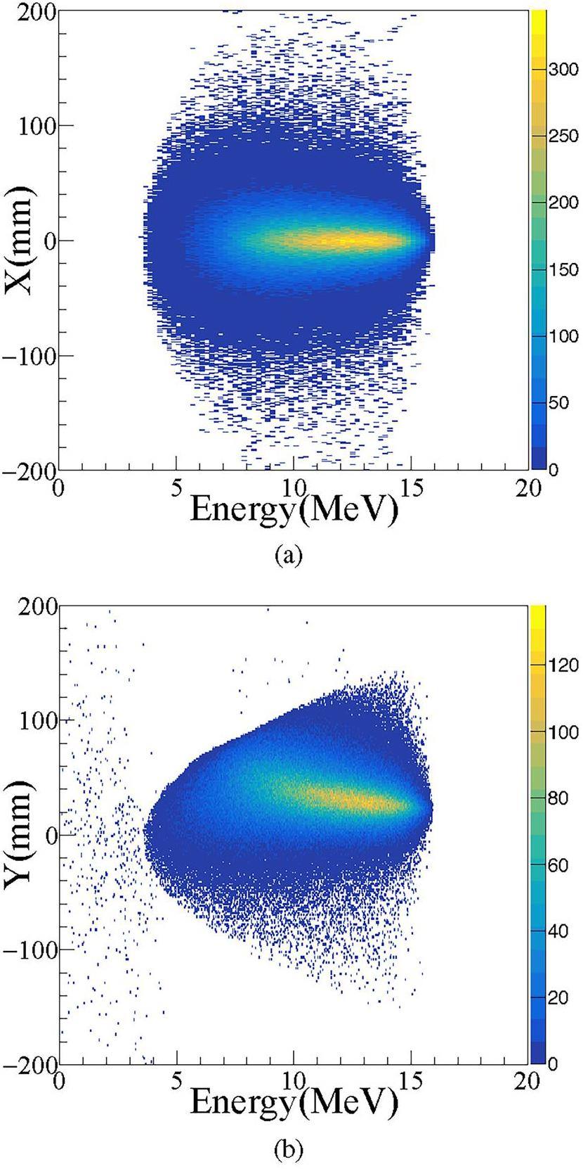
Combined with the settings mentioned in the previous section (E: 17 MeV, t: 1 mm, B: 0.3 T, z1: 90 mm, z2: 0 mm), the positron beam qualities at the target point have been analyzed carefully. The simulated positron beam is symmetrical in x direction and similar to Lorentz distribution in y direction, as shown in Fig. 10a and b. The beam spot size increases following the y direction. Mean energy of the positron spectrum is near 11 MeV with a 74% wide bandwidth. And the positron beam intensity is better than 8.9×10⁵ e+/s.
The positron beam is further investigated with a collimator. The simulated energy distributions of positron beam that are filtered by an edge length 15 mm, lead, square collimator will be improved. A positron beam of 11.9 MeV with 45% bandwidth is achievable for the square collimator with placement at
Positron beam properties in SLEGS
In the previous section, as a typical example, the process of producing a positron beam based on a 17 MeV gamma beam is carefully simulated in SLEGS. The positron beam with mean energy of 11.9 MeV, have the bandwidth better than 45% and the intensity is more than 105 e+/s. The energy of the quasi-monochromatic gamma beam at SLEGS can continuously adjusted from 0.66 MeV to 21.7 MeV with a slant Compton scattering method. Following the previous method, the simulation of producing positron beams based on different energy gamma beams have been carried out carefully. The positron beam spectrum at different energy gamma beams are shown in Fig. 11.
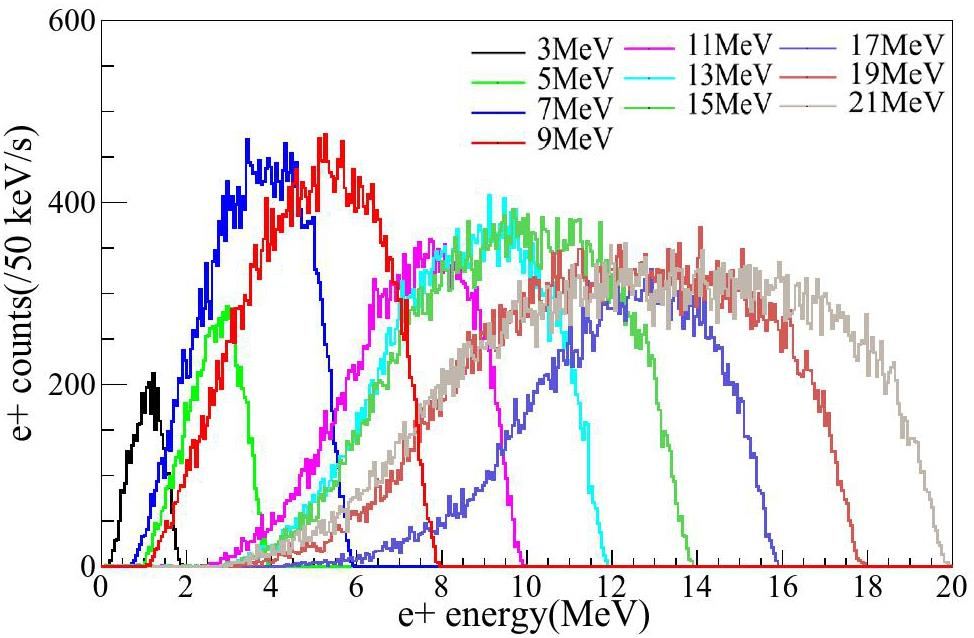
From Fig. 11, as the incident γ-ray beam energy increases, the mean energy and flux (corresponding the spectrum integral area) of positron beam increases. The incident γ-ray beam energy varies in a wide range from 3.0 MeV to 21.0 MeV. In this range, the mean energy of positron beam varies from 1 MeV to 12.9 MeV, with the flux from 3.7×10⁴ e+/s to 6.9×10⁵ e+/s and the energy resolution of near 40% in FWHM by using a square collimator with side length of 15 mm aperture.
Development status
As a construction project, the positron beam generation system in SLEGS has been funded. The gamma driven section including collimation and start signal subsection is part of the SLEGS beam line and has been built. As an independent subsystem, the PALS system has also been built separately.
The separated positron beam travels nearly 400 mm before reaching the sample. A new SLEGS PALS was designed to achieve high-level measurement using positron beam as shown in Fig. 12a. The PALS consists of two BaF2 (ϕ51 mm×20 mm, highly polished) scintillator detectors, one set of data acquisition devices, including the digital waveform processing module APV8002 from TechnoAP in Japan, the time measurement module APV8702, the high voltage module APV3003 and the front-end amplifier power supply module APV4004. The 10 ps duration gamma-ray pulse provides the start signal for the positron lifetime measurement. The stop signal consists of annihilation gamma-rays that are emitted back-to-back from the sample at 0.511 MeV. Detector-2 records the gamma-ray pulse signal, while detector-1 measures the annihilation gamma-ray of 0.511 MeV. Then, the time difference between incident gamma and annihilated gamma is recorded. In our design scheme, the start signal will come from the triggering time of laser pulses, high-frequency signals of electron beams, or direct measurements of gamma beams.
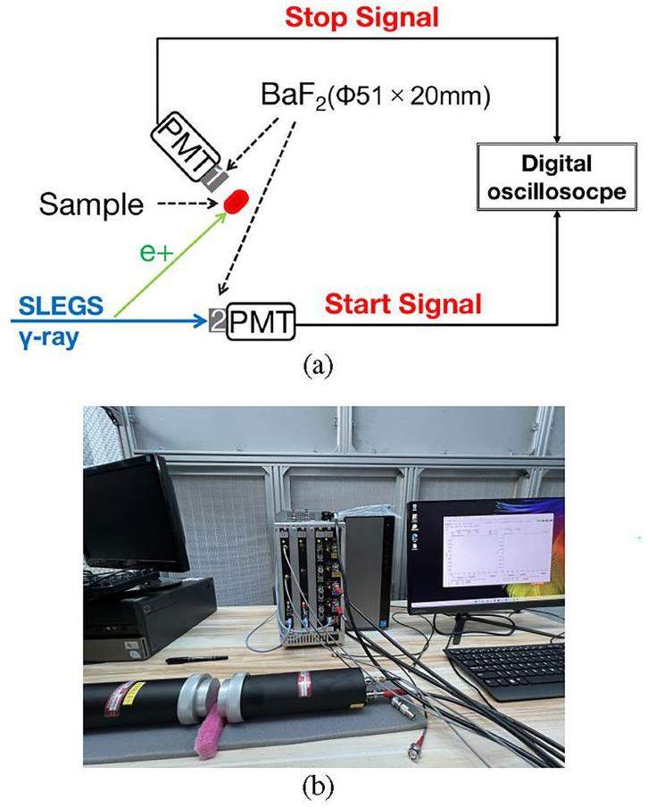
Specialized data acquisition software for PALS is available in lifetime, energy, Coincidence Doppler Broadening(CDB), and Age-Momentum Correlation(AMOC) operating modes, allowing for the measurement of time and energy, where HPGe, BaF2 and LaBr3 are used for the measurements.By feeding the response signal of the HPGe detector at 60Co to the digital waveform processing module APV8002, the acquisition parameters are configured to measure the energy resolution.The energy resolution of ~0.2% at 1.332 MeV is obtained from the data acquisition. The picture of PALS setup shown in Fig. 12b. By placing 60Co between the two scintillator detectors LaBr3, the detector signal is sent to the time measurement module APV8702, which is configured to obtain parameters to measure the time resolution. The time resolution is 159.3 ps.
The basic test experiment has been completed by choosing to inject 13 MeV gamma rays into a 1 cm Lead target at a flux of 7×10⁴ photons/s for a measurement time of one hour. The positrons will annihilate in the target and a measurement of 511 keV of gamma rays will emit a positron yield. Seven LaBr3 detectors were used in the experiment to measure the resulting 511 keV. Considering the detection efficiency of LaBr3 detector and the effect of the stereo angle, the total number of 511 keV in the full space was calculated to be 2.5×10⁸ photons/h. Gamma rays and a 1 cm Lead target are added to the simulation. Secondary gamma rays of 511 keV are collected in full space, and the total number obtained is 2.47×10⁸ photons/h, which is basically consistent with the experimental results. Verify the reliability of the simulation under these conditions.
Conclusion
This paper introduces the positron generation system designed for the SLEGS beamline in detail. The positron generation system consists of γ-ray driven section, positron generated target, magnet separation section and PALS experimental section. It will generate a new type of positron beam based on the gamma beams of SLEGS. Monte Carlo simulations have been carried out to analyze positron energy, beam flux, and spot sizes resulting from positron generated target and magnet separation section of the positron generation system. The result shows that the incident gamma energy, flux, bandwidth, targets, magnetic field, and free flight distance are directly related to the positron energy, beam flux, and spot sizes. The recommended quasi-monochromatic positron beams are produced in the energy range of 1 MeV to 12.9 MeV with a flux of 3.7×10⁴ e+/s to 6.9×10⁵ e+/s and an energy resolution of near 40% in FWHM.
Now the positron generation system is under construction in SLEGS. The gamma driven section and start signal subsection are part of the SLEGS beam line and has been built. The PALS system has also been built separately and carried out the test run. Based on the simulation work of this paper, both positron generated target and magnet separation section have been designed and are in the process of equipment manufacturing. Experimental measurements have been made and annihilation gamma ray count rates have been measured using detector arrays, which are consistent with simulations of the calculated positron intensity and expected annihilation gamma ray counts. The entire positron generation system is expected to be completed by 2025.
A design of an electron driven positron source for the internationallinear collider
. Nucl. Instrum. Meth. A. 953,A multi-parameter discrimination digital positron annihilation lifetime spectrometer using a fast digital oscilloscope
. Nucl. Instrum. Methods A 1023,Time distribution of positron annihilation in liquids and solids
. Phys. Rev. 90, 644-654 (1953). https://doi.org/10.1103/PhysRev.90.644Free volume and gas transport properties of hydrolyzed polymer of intrinsic microporosity (PIM-1) membrane studied by positron annihilation spectroscopy
. Micropor. Mesopor. Mat. 335,Positron annihilation spectroscopy characterization of formation of Helium/Hydrogen-vacancy nano-clusters in FeCr alloy
. Acta Phys. Pol. A 137, 235-237 (2020). https://doi.org/10.12693/aphyspola.137.235A new digital positron annihilation lifetime spectrometer for a single piece of micron-thickness film
. Nucl. Instrum. Methods A 1038,Digital spectrometer for coincidence measurement of doppler broadening of positron annihilation
. Nucl. Instrum. Methods A 623, 982-994 (2010). https://doi.org/10.1016/j.nima.2010.07.046Vacancies and impurities in inp studied using positron lifetime and an improved doppler-broadening spectrometer
. Appl. Phys. A 66, 435-440 (1998). https://doi.org/10.1007/S003390050690Identification of vacancies on each sublattice of SiC by coincident doppler broadening of the positron annihilation photons after electron irradiation
. Mater. Sci. Forum 363-365, 70- 72 (2001). https://doi.org/10.4028/www.scientific.net/MSF.363-365.70Nuclear data sheets for A = 22
. Nucl. Data Sheets 127, 69-190 (2015). https://doi.org/10.1016/j.nds.2015.07.002Symmetrical positron annihilation lifetime spectrometer and single-sided measurements
. J. Instrum. 14, P10021-P10021 (2019). https://doi.org/10.1088/1748-0221/14/10/P10021Experiment of positron generation using a crystal target at the KEK electron/positron linac
. Nucl. Instrum. Methods Phys. Res., Sect. B 173, 104-111 (2001). https://doi.org/10.1016/S0168-583X(00)00195-6Sclf: An 8-GeV CW SCRF linac-based X-ray FEL facility in Shanghai
. https://doi.org/10.18429/JACOW-FEL2017-MOP055A new pulse magnet control system in the KEK electron positron LINAC
. 2018. https://doi.org/10.18429/JACOW-IPAC2018-WEPAK014High-intensity and high-brightness source of moderated positrons using a brilliant γbeam
. Appl. Phys. B 106, 241-249 (2012). https://doi.org/10.1007/s00340-011-4594-0Ultrashort, mev-scale laser-plasma positron source for positron annihilation lifetime spectroscopy
. Phys. Rev. Accel. Beams. https://doi.org/10.18429/JACOW-IPAC2018-WEPAK014All-optical quasi-monoenergetic GeV positron bunch generation by twisted laser fields
. Communications Physics 5, 1-10 (2022). https://doi.org/10.1038/s42005-021-00797-9A modified positron lifetime spectrometer as method of non-destructive testing in materials
. Appl. Surf. Sci. 327, 418-423 (2015). https://doi.org/10.1016/j.apsusc.2014.11.114Development of a positron annihilation measurement system by implantation of 17 MeV gamma beam into bulk materials
. AIP Conf. Proc. 2182,Production of positrons via pair creation from LCS gamma-rays and application to defect study in bulk materials
. JJAP Conference Proceedings. https://doi.org/10.7567/JJAPCP.2.011301Positron generation through laser Compton scattering gamma ray
. Appl. Phys. Lett. 94, 1112-091112 (2009). https://doi.org/10.1063/1.3094882Photon-induced positron annihilation lifetime spectroscopy using ultrashort laser-compton-scattered gamma-ray pulses
. Rev. Scientific Instrum. 84,Source of slow polarized positrons using the brilliant gamma beam at ELI-NP. converter design and simulations
. Nucl. Instrum. Methods A 806, 146-153 (2016). https://doi.org/10.1016/j.nima.2015.10.009Status of the project for a positron laboratory at ELI-NP
. J. Phys. Conf. Ser. 791,Design and simulation of a pulsed positron beam at ELI-NP
. J. Phys. Conf. Ser. 791,Collimator system of SLEGS beamline at shanghai light source
. Nucl. Instrum. Methods A 1013,Interaction chamber design for a Sub-MeV laser-compton gamma-ray source.
. https://doi.org/10.18429/JACOW-IPAC2015-TUPJE021Quasi-monochromatic gamma beam modulation at SLEGS
. Radiat. Meas. 174,Interaction chamber for laser compton slant-scattering in SLEGS beamline at shanghai light source
. Nucl. Instrum. Methods A 1033,Development and prospect of Shanghai laser Compton scattering Gamma source.
. https://doi.org/10.11804/NUCLPHYSREV.37.2019043Commissioning of laser electron gamma beamline SLEGS at SSRF
. Nucl. Sci. Tech. 33, 87 (2022). https://doi.org/10.1007/s41365-022-01076-0Simulation study on the production of medical radioisotopes 186gRe by photonuclear reaction
. Radiat. Phys. Chem. 218,Current status and progresses of SSRF project
. Nucl. Sci. Tech. 19, 1-6 (2008). https://doi.org/10.1016/S1001-8042(08)60013-5Design and commissioning of the new SSRF storage ring lattice with asymmetric optics
. Nucl. Instrum. Methods A 1025,Bunch-by-bunch three-dimensional position and charge measurement in a storage ring
. Phys. Rev. Accel. Beams 24,Experimental studies on the x-ray single-pulse jitter at the SSRF
. Nucl. Instrum. Methods A 1025,Simulation and test of the SLEGS TOF spectrometer at SSRF
. Nucl. Sci. Tech. 34, 47 (2023). https://doi.org/10.1007/s41365-023-01194-3Energy profile of laser Compton slant-scattering γ-ray beams determined by direct unfolding of total-energy responses of a BGO detector
. Nucl. Instrum. Methods A 1063,Light output of EJ299-33A scintillator and its application
. Nucl. Tech. 45,A pulsing system for low energy positrons
. Nucl. Instrum. Meth. B. 34, 258-268 (1988). https://doi.org/10.1016/0168-583X(88)90752-5A high-performance, high-resolution positron annihilation coincidence doppler broadening spectrometer
. Nucl. Instrum. Methods A 513, 622-630 (2003). https://doi.org/10.1016/j.nima.2003.06.001Geant4 developments and applications
. IEEE Trans. Nucl. Sci. 53, 270-278 (2006). https://doi.org/10.1109/TNS.2006.869826Geant4-a simulation toolkit
. Nucl. Instrum. Meth. A. 506, 250-303 (2003). https://doi.org/10.1016/S0168-9002(03)01368-8Evaluation of the electron transport algorithm in magnetic field in EGS5 Monte Carlo code
. Physica medica: PM: an international journal devoted to the applications of physics to medicine and biology: official journal of the Italian Association of Biomedical Physics 93, 46-51 (2021). https://doi.org/10.1016/j.ejmp.2021.12.001The authors declare that they have no competing interests.

