Introduction
Medical isotope production is an important field in nuclear medicine and medical imaging [1, 2]. These isotopes are widely used in the diagnosis and treatment of various diseases, especially cancer and heart disease. Several medical isotopes can be produced in cyclotrons by bombarding targets with protons or other particles. Cyclotrons play a crucial role in medical isotope production [3-5] and offer an efficient and flexible method to meet the demands of modern medical diagnosis and treatment. Because of the current shortage of radioisotopes worldwide, medical isotope production and supply systems are actively being developed [6-8]. As is widely recognized, low-energy cyclotrons are primarily employed for proton therapy [9-11] and radioactive isotope production [12, 13]. Most existing cyclotrons use normal conducting magnet systems with a maximum field of approximately 2 T. Employing superconducting technology can easily increase a cyclotron's average field to approximately 4–5 T, and up to 9 T in some cases [14]. Therefore, a smaller magnet radius can yield higher energy, resulting in a decrease in size and overall mass (roughly proportional to
The designed cyclotron uses an internal source structure, namely, a Penning ionization gauge (PIG) [16] located near the center of the cyclotron. Owing to the low flutter in the central region, the magnetic field cannot provide adequate axial beam focusing. Consequently, the primary deficiency in the axial focusing from the magnetic field occurs in the central region. The central region needs to be well designed to obtain sufficient electrical focusing to obtain sufficient beam capture acceleration, and beam centering is crucial for achieving a high final beam quality. Therefore, a well-thought-out central electrode design is crucial to ensure sufficient electric focusing for the beam, which accounts for the complexity inherent in the central region design. The extraction system employs a stripping device to extract a proton beam, which subsequently produces the required medical isotopes by bombarding an external target. Furthermore, the conversion of H- ions into protons via stripping was used to enhance the beam extraction efficiency, potentially reaching 90% [17]. Using an external target can help keep the extraction region clean, and the stripping device size is not limited by the hill gap. The design of the main magnet must not only ensure stable beam acceleration but also provide sufficient space for installing the ion source and stripping device. This is an iterative process and a critical phase in cyclotron development. The preliminary magnet system layout was determined in accordance with magnetic circuit laws. The magnetic field was simulated through modeling and finite element analysis using OPERA/TOSCA [18]. To achieve steady beam acceleration, two conditions must be fulfilled: the magnetic field must satisfy the isochronous criterion and must provide sufficient axial focusing for the beam. Achieving field isochronism is of paramount importance, and can be accomplished by fine-tuning the sector angular width, sector spirality, and hill and valley gaps. Accurate beam dynamics calculations are essential to obtain both the field isochronicity and beam motion characteristics precisely. The DONS [19] and OPAL [20] programs [21] were used for particle tracking in 3D electromagnetic fields. OPAL is a PSI tool that can be used for cyclotron design, and is a cyclotron design code developed by Dr. Xianghui Wang at the University of Science and Technology of China.
In this study, static equilibrium orbit analysis and beam tracking were performed. The central region structure and Dee angle were optimized via multi-particle simulations. The field isochronicity was evaluated by observing the phase offset of a single particle during acceleration. The beam matching effect on the beam radial emittance was studied via beam dynamics simulations. The final beam radial emittance was minimized by carefully matching the initial phase–space ellipse of the beam to the optimal one downstream and judicious selection of the radiofrequency (RF) phase, which results in the optimal characteristics of the final beam, namely, its efficiency and emittance. An appropriate stripping point was selected by observing the variation in the beam envelope during acceleration. Subsequently, the stripping foil position and dimensions were refined by analyzing how the azimuthal position and tilt angle relative to the beam affected the beam extraction. This arrangement enables extraction by using the stripping foil's dual opposite positions to guide the beam more effectively [22]. Based on these design considerations, we present the main magnet system for a low-energy, compact superconducting cyclotron for the stable acceleration of H- ions. Because of its compact, flexible, and convenient design, this cyclotron is intended for use in medical radioisotope production.
Magnet design
To address the problem of obtaining the total energy within the confines of a magnetic constraint owing to the relativistic mass increase by a factor (1), Thomas proposed the innovative concept of an isochronous cyclotron. The isochronous field is scaled by a relativistic factor γ with respect to the radius (
(i) The magnetic field must increase with the radius to maintain an isochronous condition throughout the acceleration process.
(ii) Azimuthally varying field focusing is achieved by configuring the magnet pole into a set of three Archimedean spiral sectors while maintaining a consistent average magnetic field. The angular width is 60°. There must be sufficient axial and radial focusing for the beam to obtain an optimal transverse beam envelope during acceleration.
(iii) The radial and axial betatron tunes must be sufficiently far from dangerous resonances, or must pass through the resonance bands rapidly to ensure stable operation.
To obtain an ideal isochronous field, the Gordon method [26] was employed for the calculation, which must satisfy (2). The magnetic field value at the center for a given angular frequency can be obtained using (3) with r = 0. Upon determining the extraction energy and the magnetic field value at the center, the preliminary extraction radius estimation can be calculated using (4), where Ek is the particle kinetic energy and E0 is the remaining particle energy. The magnetic field intensity at the center was found to be 3.03 T. Due to H- lifetime issues caused by the magnetic stripping, for safety, a conservative value of 3 T must be selected for the magnetic field at the center without loss of the H- beam [27]. This central field value is significantly lower than the 4.5 T central field of the existing ION-12SC small cyclotron, making it suitable for stripping extraction. The ion's angular frequency is calculated as
| Item | |
|---|---|
| Cyclotron type | Compact, Isochronous |
| Accelerated particle | H- |
| Final energy (MeV) | 11 |
| Current (μA) | 50 |
| Central/extraction field (T) | 3.032/3.067 |
| Sectors/Sector shim type | 3/Archimedean spiral |
| Spiral angle (maximum) (°) | 64 |
| RF system | One 197° Dee, 30 kV |
| Injection type | Internal PIG source |
| Operating RF harmonic | 1 |
| RF frequency (MHz) | 46 |
| Extraction radius (mm) | 160 |
| Hill gap (mm) | 30 |
| Operating current density (A/mm2) | 170 |
| Cyclotron height (mm) | 730 |
Based on the magnet parameters listed in Table 1, a 1/3 model was created using SOLIDWORKS and subsequently imported into OPERA/TOSCA for simulation. The simulation model is shown in Fig. 1a. After a series of simulation iterations, the mean field was adjusted to match the isochronous field in the median plane using the Gordon method. Figure 1b shows a comprehensive representation of the median-plane mean field that satisfies isochronicity. The central field B0 is 3.032 T, the minimum field is 2.365 T, and the maximum field reaches 3.643 T. Various techniques [29] can be employed to approach the ideal isochronous field, including sector angular width modifications, spiral angle adjustments, and refining the hill and valley gaps, among others. The sector angular width and spiral angle remained unchanged throughout the optimization process. Because the RF system was not installed in the valley, the magnetic field was adjusted by modifying the valley gap at different radii. This can be achieved by adding magnets of specified sizes at different radii in the valley. Due to the compact cyclotron size, the advantage of doing this is that it is easy to implement in practice. Additionally, if necessary, other particles can be conveniently accelerated by adjusting the size of the added magnets according to the isochronous field requirements. This method has lower precision requirements for coil positioning than adjusting the superconducting coil, and offers higher adjustability.
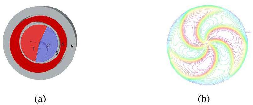
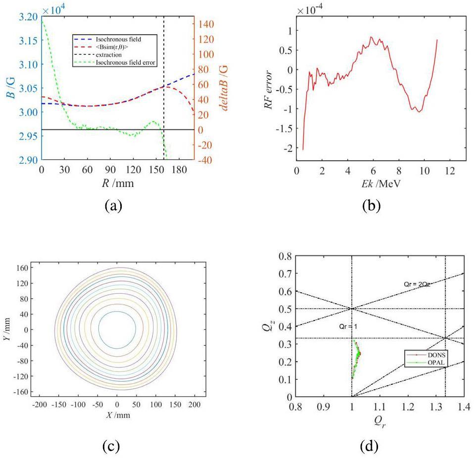
Figure 2a shows the ideal isochronous field obtained via the Gordon method and the azimuthal mean field distribution obtained by the model, plotted as a function of R. It can be seen that the deviation between the simulated field and the ideal isochronous field remains within 10 G throughout the acceleration region. To achieve weak focusing in the central region and satisfy the axial stability requirement of the particles, the magnetic field in the range of r = 0–20 mm exceeds the theoretical isochronous field. Betatron frequencies were calculated from small perturbations of the equilibrium orbit. Figure 2b shows the orbital frequency error variation with energy and the orbital frequency error throughout the entire acceleration process, maintaining a remarkable low level within 0.02%. From this perspective, an isochronous field error within 10 G falls within the acceptable error range. This error was verified more precisely via beam dynamics simulations in the subsequent stages. Besides satisfying the isochronous condition, the magnetic field distribution must deliver an ample transverse force to effectively focus the particle beam. Radial and vertical beam tunes are intricately linked to various magnetic sector parameters, including the radial field index, spiral angle, and field flutter. The working point of the cyclotron was effectively separated from a dangerous resonance state by fine-tuning the spiral angle of the magnetic pole. Figure 2c shows the static equilibrium orbit (SEO) ringing from 1 to 11 MeV. Each orbit oscillates around a specific radius, and the concentric distribution of these orbits demonstrates effective isochronous field regulation. Figure 2d shows a working point diagram for the 11-MeV cyclotron design, calculated from the magnetic field map produce by OPERA using OPAL and DONS. As can be seen, there is little difference between the calculations by the two codes. Notably, the diagram demonstrates that the particles effectively avoid crossing dangerous resonance lines (the dotted lines represent different resonance lines) throughout the acceleration process.
Central region
The central region structure design significantly affects the intensity and quality of the extracted beam [34, 35]. To enhance the transmission efficiency in the central region and quality of the extracted beam, the central area design should consider the following aspects:
(i) The central region structure should have a fixed phase acceptance. Maximizing the central region phase acceptance is crucial for enhancing the beam transport efficiency within the central region.
(ii) Reducing the beam phase dispersion and optimizing the beam centering in the first few turns play decisive roles in improving the quality of the extracted beam.
(iii) The beam quality at the point of entry into the extraction system is a critical factor that influences both the extraction efficiency and the quality of the extracted beam.
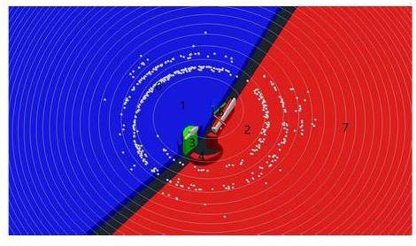
The RF resonator, with a Dee radius of 180 mm, accommodates itself between the spiral pole faces. The Dee plates were 3 mm thick and spaced 10 mm apart. A structural model of the Dee and central regions was used to determine the electrical field distributions employed in the beam dynamics analysis. Figure 3 shows the model structure for the central region. A PIG-type ion source with an internal chimney radius of 2 mm was used. The dimensions of the ion source opening slit were 0.2 mm × 2 mm. The most commonly used shape for the source slit is one whose axial size is several times greater than its radial size [30]. The gap between the Dee and dummy Dee was 6 mm, with the peak voltage set at 30 kV. Compared with the central region design of the ION-12SC, this design increases the gap between the Dee and dummy Dee, which enhances the Dee voltage, improves the acceleration efficiency and reduces the acceleration time.
In the case of a PIG-type ion source, where the initial beam energy is typically low, the time required for the particles to traverse the first acceleration gap is non-negligible. At the ion source output slit, the beam energy typically ranges between 5 and 20 eV, with an emittance of approximately 1.3π mm mrad [31]. When generating the initial particle distribution injected from an internal source, the dependence of the extracted beam intensity on the extraction voltage amplitude must be considered, as described by the Child-Langmuir law [33]. According to Kirkpatrick's formula [32], ignition occurs when the value is higher than 1.3 Kirkpatrick in the experiment (1 Kirkpatrick equals 86 kV/cm at 46 MHz). After the preliminary calculation, the width of the first acceleration gap was approximately 3.5 mm. The first acceleration gap significantly influences the particle trajectory and other beam dynamic characteristics; therefore, the design of the first acceleration gap is the main consideration in the central region design. In the central structure of the internal ion source, the beam parameters can be adjusted by manipulating the position and direction of the ion source opening slit. Based on the beam centering and the energy gain in the initial turns of the particle, the ion source position, initial particle direction, and starting RF phase at the ion source output slit were optimized. Further details are provided in the following section. Following the ion source placement optimization, optimal beam centering was attained, the ion source was positioned at (-0.2 mm, -7 mm), and the radius was 7.0029 mm.
It is necessary to analyze the particle acceleration process with various initial phases because the central region exhibits different acceptance characteristics for particles injected at different times. First, in terms of energy gain, Figs. 4a and b clearly show the particle trajectories with different initial phases in the first few turns and the energy gain through the first acceleration gap. It is evident that the particle energy gain with initial phase distributions of -90 to -40° and 0 to 90° is significantly smaller than that of particles with initial phase distributions of -40 to 0°. Second, the analysis was conducted from the viewpoint that the particles were subject to focusing/defocusing. According to theoretical analysis, particles approaching the phase where the electric field is about to decrease experience a greater focusing effect as they pass through the acceleration gap centerline. Figure 4a reveals that axial defocusing acts on particles passing through the first acceleration gap when the initial phase distribution is between -90° and -60°, while axial focusing is applied to particles with a phase between -60° and 0°. The above analysis indicates that particles with initial phases ranging from -40 to 0° exhibit better energy gain and focusing effects.
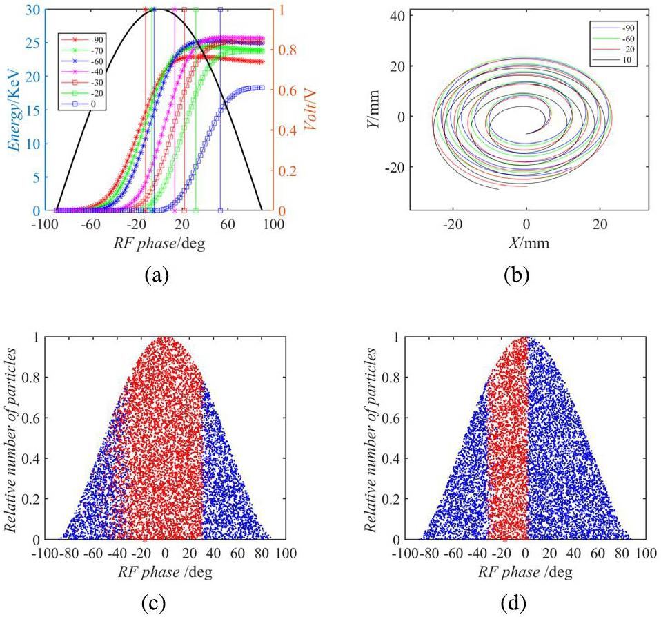
The central region must be designed in such a way to ensure that the beam undergoes sufficient axial focusing as it traverses the first few acceleration gaps. This is crucial because of the low initial energy at the ion source output slit, which defocuses the beam. The initial RF model used an 180° Dee structure, in which case the phase of the second pass through the accelerated gap midline is 170° when the particles experience axial defocusing for the first few turns, resulting in a low transmission efficiency of 26.5%. Optimizing the Dee structure enhanced the transmission efficiency in the central region by providing axial focusing during the second acceleration gap in the initial turns. By selecting a single 197° Dee structure, the optimized central region transmission efficiency is 62%. The multi-particle simulation results show that particles within a range of 0 to 30° can traverse the central region but were not successfully extracted because of the growing de-centering of the beam, as shown in Fig. 4d. The multi-particle simulation results also indicate that the phase acceptance in the central region ranged from 30 to 30° without the phase selector. Under these conditions, the transmission efficiency for the first few turns was 62%, with only 35% achieving full energy acceleration. A phase selector was incorporated into the central region to selectively discard particles with initial phases ranging from 0° to 30°. This measure aims to reduce the energy dispersion and radial oscillation amplitude of the extracted beam, thereby improving its overall quality. Furthermore, particles with phases between 0 and 30° were lost in other parts of the cyclotron, potentially causing damage. Therefore, it is preferable to add a phase selector to the central region to ensure that the particles are lost within the phase selector. Periodically changing the phase selector is more convenient and effective than addressing the potential damage caused by particle loss in other areas. Finally, the particle transmission efficiency in the first few turns was 40%, with 30% capable of accelerating to full energy. The trajectory of the beam particles captured during central region acceleration is shown in Fig. 3.
Beam dynamics calculations
Single-particle tracking
Field isochronism and tune optimization are crucial considerations in cyclotron magnet design. Therefore, it is essential to conduct a thorough assessment of the field isochronism and carefully examine both axial and radial beam focusing through single-particle tracking. The radial and axial betatron tunes of the particles were studied, and the working point diagram of the cyclotron based on the SEO was constructed, as discussed in the previous section. Subsequently, a comprehensive exploration of the beam's properties during the acceleration phase was conducted. The phase offset within the accelerating region was obtained from the beam dynamics analysis to ensure that it satisfied the isochronous requirements (see Fig. 5c. The acceleration voltage experienced by a particle as it traverses the acceleration gap is described as V=V0, where V0 is the maximum RF system voltage.
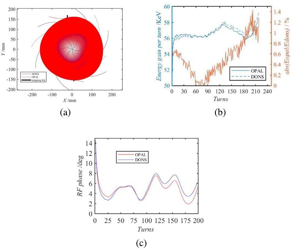
The single-particle tracking results revealed that the particles demonstrated enhanced beam centering characteristics and energy gain. The first-turn energy gain was 53.3 keV, corresponding to a radius of 10 mm. Consequently, the estimated distance of the ion source from the machine center was approximately 7 mm. The trajectory of a single particle was calculated using OPAL and DONS. Figure 5a shows the trajectory of an H- particle undergoing acceleration from 20 eV to 11 MeV (with the bunch position at approximately r = 155 mm). The particle reached 11 MeV after 191 acceleration turns. This indicates the high effectiveness of beam centering as well as the consistency in the tracking results between the two codes. Figure 5b shows the particle energy gain per revolution, and the kinetic energy of the H- ion as a function of the number of turns throughout the acceleration process. The computed energy gain per particle turn was approximately 57 KeV, with a negligible relative error within 1.5% between the results obtained by the two codes. Figure 5c shows the RF phase of the H- ion as it traverses the Dee gap. The mean-field dependence of the number of turns slightly deviated from the isochronous curve. This led to slippage in the RF phase of the particles. As shown in Fig. 5c, the total RF phase excursion during the acceleration process remains within 5°, reflecting the high isochronicity degree of the magnetic field. The similarity in the trends of the phase excursions calculated using the two codes further confirms the accuracy of the simulation results.
Tracking of an ensemble of particles
Tracking an ensemble of particles is necessary to investigate the impact of the magnetic field on beam focusing and transmission efficiency. Calculations were conducted using 10,000 macroparticles. Observations show an increase in emittances (projections on phase-space planes) as the beam undergoes acceleration within the central region. The beam exits the ion source opening slit and accelerates to 0.5 MeV after 10 turns, the radial beam emittance is approximately 3π mm mrad. The results show that the radial emittance increases from 3π to 10.15π mm mrad (at Ek = 11 MeV) when a mismatched distribution is observed. This phenomenon results in degraded beam quality during extraction. To reduce this effect, the initial beam distribution was comprehensively studied to optimize the quality of the extracted beam.
Subsequently, the influence of the radial motion stable region [36] on beam emittance throughout the acceleration process was studied. The initial particle distribution from the ion source slit was assumed to be an uncoupled Gaussian distribution. The particle bunch evolves under the influence of the fields generated by a simplified azimuthally symmetric cyclotron. It self-generated into a circular stationary distribution after several initial turns. The primary focus was on achieving radial matching. After obtaining the particle SEO at an energy of 0.5 MeV, the deviations in the particle's position (r) and radial momentum (pr) from the SEO were adjusted, and these parameters were recorded after each turn. The radial phase–space motion of the beam near the SEO was obtained via different phase–space trajectories under different initial conditions, as shown in Fig. 6a. The red area indicates the stable region. The Twiss parameters of a beam with an emittance of 3π mm mrad in the stable region can be easily obtained.
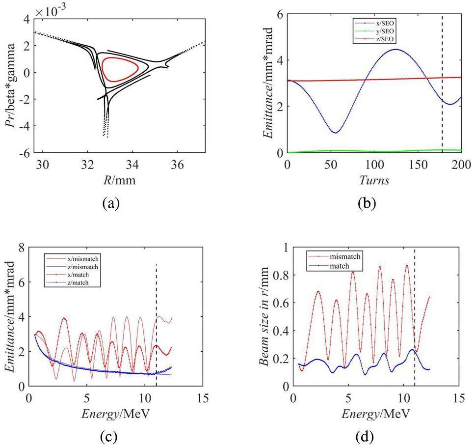
To confirm the compatibility of this distribution, the particles were tracked for multiple turns within the cyclotron at a 0.5-MeV beam energy without an RF system. As shown in Fig. 6b, the observed slight beam emittance oscillation can be attributed to the inherent non-linearity within the magnet system. The periodic nature of the radial beam emittance oscillation without acceleration stems from the non-integer values of the radial betatron tunes Qr, which range between 1.004 and 1.027. Similarly, the observed marginal axial beam emittance fluctuations are attributed to the axial betatron tunes falling within the range of 0.0998 and 0.32. These findings align with the theoretical expectations.
Herein, a detailed beam emittance evolution study during the acceleration process is presented for two scenarios: a mismatched beam and a beam with particles distributed within radial stability. As shown in Fig. 6c, the simulation results indicate that the radial equilibrium of the matched beam exhibits significantly lower emittance than that of the mismatched beam throughout the acceleration process, with the emittance of the former decreasing to 2.36π mm mrad at the extraction. Fig. 6d shows the radial envelope evolution for the two scenarios during acceleration. It is evident that the mismatched beam experiences pronounced radial oscillations spanning 0.1–1.2 mm, whereas the matched beam exhibits a considerably narrower variation range in its radial envelope, fluctuating between 0.08 and 0.26 mm. This reduction in beam emittance and envelope enhances the quality of the extracted beam and improves the extraction efficiency.
Extraction system
It is widely recognized that cyclotrons used in radioisotope production typically have a lower beam quality than those intended for fundamental research and cancer therapy. Consequently, the cyclotron design presented here adopts the stripping extraction method commonly used in negative-ion accelerators, which has the advantages of a simple structure and high extraction efficiency. The optimum stripping point is a crucial factor that affects the quality and transmission efficiency of the extracted beam. An ensemble of particles was used to determine the emittance, envelope, and other extracted beam parameters. The precise location of the stripping foil was determined based on the real-space behavior of the tracking results in two adjacent turns, particularly near the 11-MeV beam energy. Determining the stripping point for the 11-MeV extracted energy relies on two key criteria:
(i) The radial beam envelope is minimal in each turn, especially near the 11-MeV energy value.
(ii) When condition (i) is satisfied, the position of the beam emittance is at a minimum in each turn around an energy close to 11 MeV.
These two requirements can be used to determine the appropriate stripping point. The exact position of the stripping foil was precisely determined by studying its azimuthal and tilt angles.
Effective vertical focusing can be achieved by selecting the azimuthal position of the stripping foil. The phase–space distributions extracted at different stripping foil azimuth angles are shown in Figs. 7a and 7b. It is notable that while the axial distribution remains nearly elliptical owing to the characteristics of multi-turn extraction, the radial distribution of the bunch becomes non-elliptical as it traverses the stripping foil. This property contributed to an increase in the energy spread of the extracted beam. An azimuthal angle of 97° was adopted for beam focusing optimization. It is widely recognized that the angle between the stripping foil and the beam's normal direction acts as a focusing or defocusing lens in the radial direction while having no impact on the axial direction. Figures 7c and 7d show the extracted beam envelope as a function of the stripping foil rotation angle. This angle has a significant influence on the radial beam envelope, whereas its effect on the axial beam envelope is relatively minor. A tilt angle of 4° was adopted to minimize the extracted beam envelope.
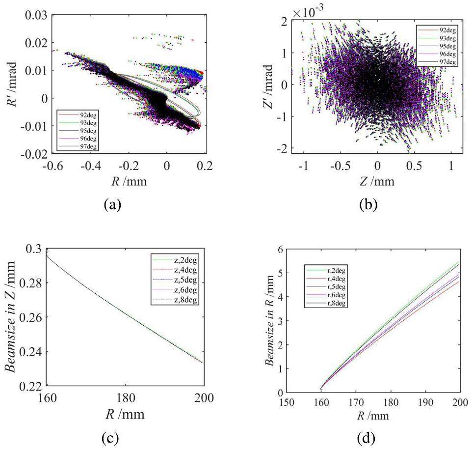
Stripping extraction has the advantages of a high extraction efficiency and simple operation; however, because of the existence of a large number of overlaps in the extraction region, stripping extraction is challenging. Therefore, a dual-opposite stripping foil device was used to improve the quality of the extracted beam. Figure 5a shows the basic principle of using a dual-opposite stripper-extraction cyclotron for extraction. The black line indicates the stripper location in the valley. The beam was efficiently extracted by using two stripping foils positioned at an azimuthal difference of 175.26°. Simulation results showed that 96% of the macroparticles were successfully extracted using the first stripping foil; the remaining 4% were stripped and extracted using the second stripping foil. The beam size at the stripping foil was 0.5 mm × 3.4 mm. It is worth noting that the radial emittance experienced a modest increase from 0.5π to 1.1π mm mrad, whereas the axial emittance exhibited a negligible change of approximately 0.3π mm mrad. The energy spread of the beam during extraction was 0.0098 MeV.
Conclusion
This paper presents a new compact superconducting cyclotron design for medical isotope production, with a 11-MeV energy and a 50 μA beam current for H- ions. Compared with ION-12SC, it offers a higher extracted beam intensity, which enhances the production efficiency and makes it more suitable for PET isotope production. This study covered the magnet system design, central region configuration, beam dynamics analysis, and extraction system design. The initial size of the magnet system was established according to magnetic circuit theory. Owing to the complexity of the magnet system design, precise beam dynamics simulations were performed to fine-tune the magnetic sector dimensions. After multiple iterations, the final magnet dimensions were 200 mm in diameter and 730 mm in height. The deviation between the obtained and isochronous fields remained well within 10 GS, and the orbital frequency error was on the order of 10-4. Notably, beam dynamics calculation results showed that the tune does not intersect any hazardous resonance lines during acceleration.
The proposed RF system employs a single 197° Dee model to provide axial focusing for the beam during the first few turns. After optimization, the PIG-type ion source is positioned at (-0.2 mm, -7 mm). Assuming an ion source output slit energy of 20 eV and initial beam emittance of 1.3π mm mrad, the transmission efficiency of the central region was enhanced from 26.5% to 40% through the iterative modification of the central electrode structure. The results revealed that, after 191 acceleration turns, the particle's energy reached 11 MeV at a radius of 155 mm. Notably, the RF phase extrusion remained within 5° throughout the process. Additionally, the impact of beam emittance variations on the emittance of the extracted beam and that of the initial beam distribution on beam emittance during the acceleration process were investigated. It is worth noting that selecting the initial particle distribution in the radial stable region can effectively reduce emittance growth during acceleration. Consequently, the extracted beam emittance decreased from 3.92π to 2.36π mm mrad. Furthermore, the radial beam envelope oscillation range exhibited a significant improvement, decreasing from 0.1–1.2 mm to a much narrower range of 0.08–0.26 mm.
Stripping extraction was adopted because of its high efficiency and the fact that its beam quality meets the requirements of a cyclotron for radioisotope production. The stripping point at 11 MeV was calculated by determining the methodology of finding the minimum beam size at the stripping foil, using the phase–space distribution obtained from the multi-particle simulations, and conducting a detailed simulation of the extraction trajectory for the 11-MeV energy beam. The impact of the stripping foil azimuthal position and the tilt angle between the stripping foil and beam on the quality of the extracted beam were studied. A stripping foil azimuthal position at 97° and a tilt angle of 4° were adopted. Notably, the energy spread was 0.0098 MeV for a 11.12-MeV energy.
Superconducting cyclotron for flash therapy
. Nucl. Instrum. Nucl. Instrum. Methods Phys. Res. Sect. A 986,Feasibility study on the DFP adoption of the medical cyclotron decommissioning in Republic of Korea
. Nucl. Sci. Tech. 25,Overall design of CYCIAE-14, a 14 MeV PET cyclotron
. Nucl. Instrum. Methods Phys. Res. Sect. B 269, 24 (2011). https://doi.org/10.1016/j.nimb.2011.04.049Physics design of a 70 MeV high intensity cyclotron, CYCIAE-70
. Nucl. Instrum. Methods Phys. Res. Sect. B 269, 24 (2011). https://doi.org/10.1016/j.nimb.2011.04.052Low-cost target system for neutron activation using a medical cyclotron. Application to the non-destructive analysis of gold and silver
. Appl. Radiat. Isot. 184,Transverse emittance measurement for the heavy ion medical machine cyclotron
. Nucl. Sci. Tech. 30, 184 (2019). https://doi.org/10.1007/s41365-019-0699-7Cross-section measurement of thulium radioisotopes with an 18 MeV medical PET cyclotron for an optimized 165Er production
. Appl. Radiat. Isot. 200,Alternative routes for 64cu production using an 18 MeV medical cyclotron in view of theranostic applications
. Appl. Radiat. Isot. 191,Design and development of the beamline for a proton therapy system
. Nucl. Sci. Tech. 32, 138 (2021). https://doi.org/10.1007/s41365-021-00975-yBeam optics and isocenter property of SC200 proton therapy gantry
. Nucl. Sci. Tech. 29: 112 (2018). https://doi.org/10.1007/s41365-018-0446-5Developments for 230 MeV superconducting cyclotrons for proton therapy and proton irradiation
. Nucl. Instrum. Methods Phys. Res. Sect. B 406: 224-249 (2017). https://doi.org/10.1016/j.nimb.2016.11.010Development of a superconducting magnet for a compact cyclotron for radioisotope production
. IEEE Trans. Appl. Supercond. 26: 1-4 (2016). https://doi.org/10.1109/TASC.2016.2548429Review of cyclotrons for the production of radioactive isotopes for medical and industrial applications
. Rev. Accel. Sci. Technol. 4, 103-116 (2011). https://doi.org/10.1142/S1793626811000574Medical cyclotrons
. Rev. Accel. Sci. Technol. 2, 133-156 (2009). https://doi.org/10.1142/S1793626809000272Design and field measurement of a dipole magnet for a newly developed superconducting proton cyclotron beamline
. Nucl. Sci. Tech. 29: 133 (2018). https://doi.org/10.1007/s41365-018-0463-4Study on a cold-cathode H- PIG-type ion source
. Nucl. Sci. Tech. 24:Characterization of graphene stripper foils in 11-MeV cyclotrons
. Phys. Procedia 90, 369-373 (2017). https://doi.org/10.1016/j.phpro.2017.09.034Physical design of the beam injection system of a superconducting cyclotron using DONS code
. Nucl. IEEE Trans. Appl. Supercond. 31, 8 (2021). https://doi.org/10.1109/TASC.2021.3107823Computer codes for beam dynamics analysis of cyclotronlike accelerators
. Phys. Rev. Accel. Beams 20,Stripping extraction calculation and simulation for CYCIAE-100
. Chin. Phys. C 33, 42 (2009). https://doi.org/10.1088/1674-1137/33/S2/011The paths of ions in the cyclotron I. orbits in the magnetic field
. Phys. Rev. 54, 580 (1938). https://doi.org/10.1103/PhysRev.54.580Design and Construction of the Main Magnet for a 230-MeV Superconducting Cyclotron
. IEEE Trans. Appl. Supercond. 28, 3 (2018). https://doi.org/10.1109/TASC.2017.2777469Physics design of CYCAIE-100
. Chin. Phys. C 33, 33 (2009). https://doi.org/10.1088/1674-1137/33/S2/009H- superconducting cyclotron for PET isotope production
. Phys. Part. Nucl. Lett. 11, 774-787 (2014). https://doi.org/10.1134/S1547477114060132Design and test of superconducting magnet for 200 MeV proton cyclotron
. Cryogenics 97, 122-125 (2019). https://doi.org/10.1016/j.cryogenics.2018.11.004An improved matrix method for magnet shimming in compact cyclotrons
. Nucl. Instrum. Methods Phys. Res. Sect. A 620, 121-127 (2010). https://doi.org/10.1016/j.nima.2010.03.135Central region design in a compact cyclotron
. Phys. Part. Nucl. Lett. 16, 34-45 (2019). https://doi.org/10.1134/S1547477119010114Design study of an ultra-compact superconducting cyclotron for isotope production
. Nucl. Instrum. Methods Phys. Res., Sect. A. 763, 6-12 (2014). https://doi.org/10.1016/j.nima.2014.06.013criterion for vacuum sparking designed to include both rf and dc
. Rev. Sci. Instrum. 28, 10 (1957). https://doi.org/10.1063/1.1715731Two-dimensional Child–Langmuir law of planar diode with finite-radius emitter
. Appl. Surf. Sci. 251, 1-4 (2005). https://doi.org/10.1016/j.apsusc.2005.03.160Spiral inflector and central region study for three cyclotrons at CIAE
. Nucl. Instrum. Methods Phys. Res. Sect. B 261, 1-2 (2007). https://doi.org/10.1016/j.nimb.2007.04.230Beam dynamics study for a small, high current 14 MeV PET cyclotron
. Nucl. Instrum. Methods Phys. Res. Sect. B 269, 24 (2011). https://doi.org/10.1016/j.nimb.2011.04.050The authors declare that they have no competing interests.

