Introduction
The GCT is an important component of the safety systems of nuclear power plants. When the steam turbine load decreases sharply, the reactor power cannot decrease synchronously, resulting in an instantaneous core power that does not match the steam turbine load. In this case, a steam bypass system is used to provide an "artificial" load for the reactor, maintain the power balance of the primary and secondary circuits, and ensure the safety of the power plant [1]. Related research has been conducted to understand the mechanism of steam bypass discharging.
Jia [2, 3] performed a comparative analysis of a passive nuclear power plant and an improved second-generation nuclear power plant, showing that the control logic and control objects of the steam-discharging system of the passive nuclear power plant were improved. Duk et al. [4] simulated and studied the capacity changes of steam discharge valves under power increasing conditions and found that the most suitable setting values for the feedwater control system (FWCS) and proportional band of the steam dump control system (SDCS) were 0.6 and 15.0, respectively. Lee [5] investigated the parameter changes of a steam emission control system under load rejection conditions when the main feedwater was insufficient, and explored the optimal setting parameters for the steam emission control system. Wang et al. [6] established a real-time simulation model of a steam discharge control system that was in good agreement with the operation data of a nuclear power plant, laying a good foundation for the next step of parameter optimization and semi-physical simulation. Lu et al. [7, 8] simulated the steam discharge of a second-generation nuclear power plant during a shutdown accident, and verified the scope of application of the steam discharge system and its safety under different working conditions. Relevant studies [9–11] have put forward reasonable response suggestions by simulating and analyzing the control logic of a steam discharging system to cope with power reduction, reactor shutdown of units, and other accident conditions. Fan et al. [12, 13] analyzed the transient response characteristics of a full exhaust condenser in the steam discharge system of a pressurized water reactor (PWR) nuclear power plant, which is of great significance in the design of steam bypass discharge control systems for steam turbines. Zhao et al. [14] examined the response process of the system when the GCT121VV was not normally opened under the condition of a full-power turbine trip only. The control of the generator unit was discussed under the conditions of this type of problem.
Studies on the GCT of an AP1000 nuclear power plant [15–17] show that the steam bypass system combined with the reactor power control system can make the AP1000 design bear the load rejection or turbine power transition without reactor jump, atmospheric emission, or triggering action of the safety valve of the pressurizer and steam generator (SG). Tian [18], based on a theoretical analysis, used the method of list analysis to introduce the steam dump valve site layout and the design, structure, and magnetic valve control of the SDCS so that the related personnel could better understand the AP1000 steam dump valves. Dong [19] elaborated on the operation mode, control, and locking of the steam emission system and conducted accident analysis under the anticipated transient without scram (ATWS), providing guidance for operation and maintenance work. Zhou [20] controlled the primary circuit average temperature and main steam collection pressure, simulated the steam discharge process, and obtained a better solution. Zhang [21] introduced an automatic control scheme for the atmospheric discharge valve in which the HPR1000 automatically triggered the atmospheric discharge valve for automatic regulation by using a safety injection signal. It can complete the rapid cooling of the reactor coolant circuit and greatly reduce the safety risks caused by personnel miscalculation and misoperation. Sui et al. [22] used RELAP5 software to analyze the response characteristics of the HPR1000 primary circuit under different steam direct emission (VDA) conditions, showing that the emission capacity of the VDA is proportional to the reactivity feedback, and proposed that the VDA should be placed before a certain critical point. Song et al. [23] studied the accident conditions of a U-tube rupture (SGTR) in an APR1400 nuclear power plant and revealed that an atmospheric steam discharging system can significantly slow down the core melting process. Chen et al. [24] used RELAP5 to simulate the small break loss of coolant accident (SBLOCA) of a million-kW nuclear power plant and found that GCT-a combined with a pressurizer spray could effectively reduce the primary circuit pressure, enable the safety injection tank to be put into operation, supplement the primary circuit coolant, and effectively control the accident. Cai et al. [25] studied the bypass control function of an AP1000 steam turbine and found that it could meet any transient operating conditions of the unit when used in conjunction with reactor power without generating emergency shutdown and safety valve actions. Liu et al. [26] used RELAP5 code to build a control model and conducted variable load dynamic simulations on a SG. The results showed that the control model responded quickly and exhibited good stability effects on the coolant temperature and pressure.
In conclusion, the study of steam discharge characteristics under accident conditions using numerical simulations has received significant attention, and some achievements have been made. However, the parameter coupling characteristics of the primary and second circuits of steam discharge under SBLOCA conditions still need to be further analyzed. In this study, to explore the influence of the steam discharging system on the characteristics of the primary circuit, a complete nuclear power plant model was established using the RELAP5 software. The response characteristics of the primary circuit pressure, flow rate, temperature, and other parameters were investigated when operating the steam discharging system and primary circuit safety injection system under the condition of five different SBLOCAs combined with whole-plant power failure.
RELAP5 modeling and steady-state verification
RELAP5 modeling
A typical three-loop PWR nuclear power plant system model was established using the RELAP5 code. The model included a pressure vessel and core, three coolant loops, pressurizer (232), break (502), residual heat removal system (RRA; 702 outlet; 721, 741 inlet), safety injection system (510–590), main steam and main feed system (280–486), auxiliary feed system (600–620), steam bypass system (295–495), SG, and other required equipment.
The RELAP5 code uses a control body as a unit for calculation. As the number of nodes gradually increases, the calculation deviation gradually decreases until it can be ignored, while the calculation time increases [27, 28]. After comprehensive consideration, the optimal number of nodes was determined, as shown in Fig. 1, where the core key section is divided into 20 nodes (the active zones range from 5 to 16 nodes).
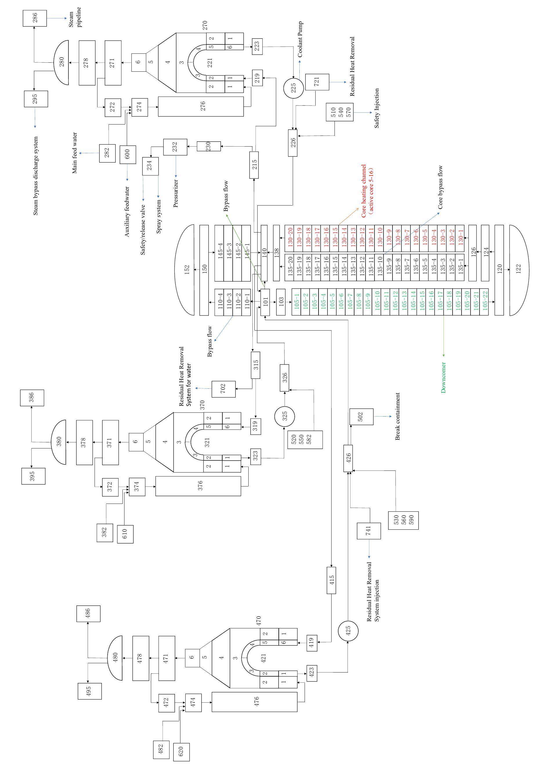
The reactor coolant flows from the pressure vessel inlet (101) into the descending annulus (105) to the bottom of the pressure vessel (120), enters the reactor core through the core support plate (124) and lower grid plate (126), and generates heat by nuclear fission of the fuel element. The coolant flows through the upper grid plate (138) and is mixed with the core side flow (135), guide tube side flow (110–145), and core spoke side flow (101–140). The mixed coolant enters the three-loop hot legs from the pressure vessel outlet (140). Taking the first loop as an example, the coolant in the first loop flows from the outlet of the pressure vessel to the lower head (219) of the SG, enters the U-shaped heat transfer tube side (221) for heat exchange, and flows through the pump (225) from the lower head (223) to the pressure vessel. The secondary main feedwater (282) is mixed with the fluid (272) and separated from the SG steam water separator (371). It enters the bottom of the SG through the U-shaped shell side (270) to exchange heat with the primary circuit. After heat exchange, the steam enters the main steam pipeline (286) through the steam water separator and dryer (380), and then enters the main feedwater cycle again after the steam turbine performs power and post-treatment.
Treatment of GCT cooling strategy
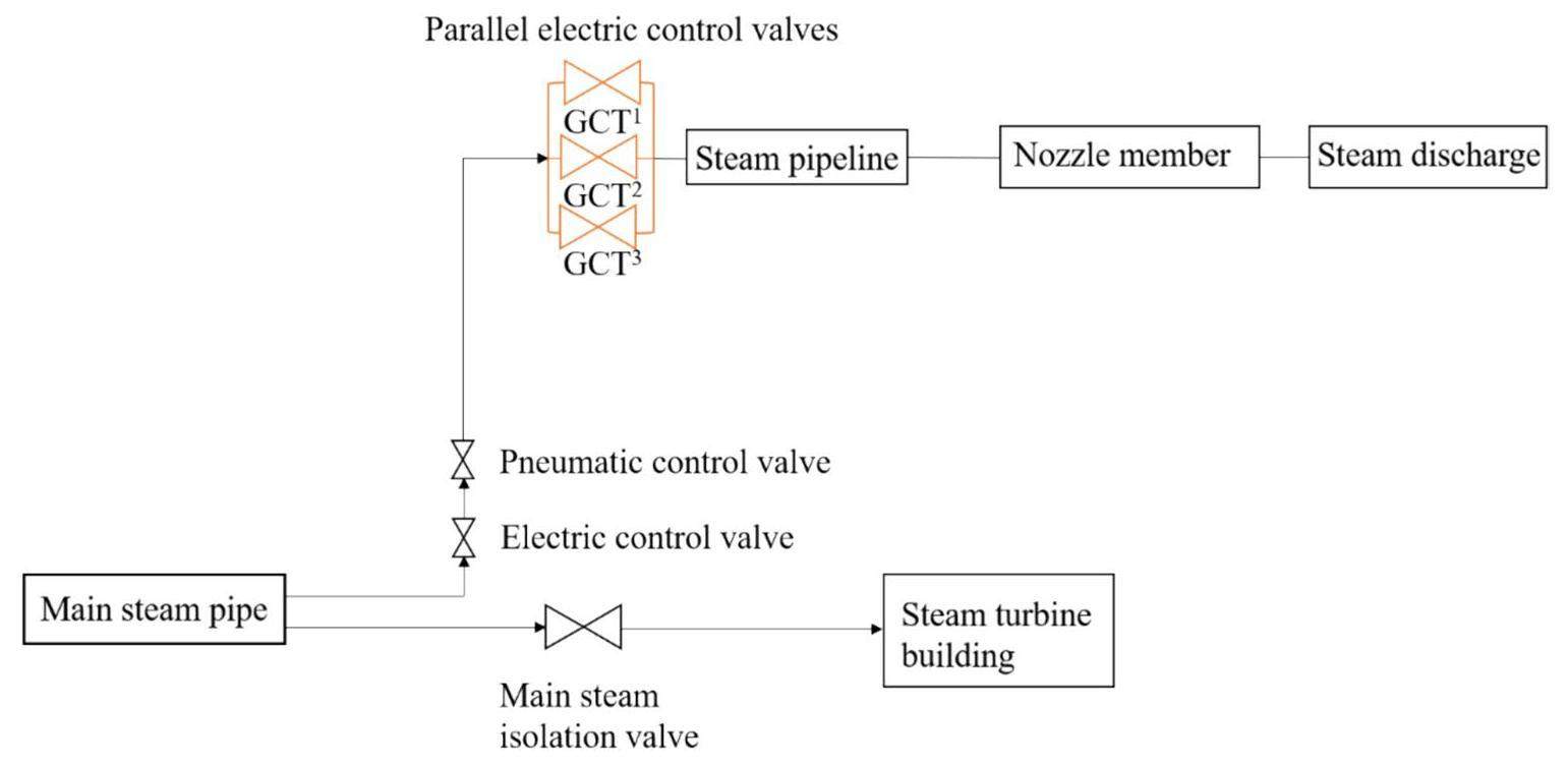
To ensure a safe cooling rate of the core during the rapid cooling process, the average cooling rates at the reactor core inlet and outlet were set and maintained at 100 K/h after the GCT was operated [29]. As shown in Fig. 2, three groups of parallel electric control valves (GCT1, GCT2, and GCT3) are mounted in the GCT bypass discharge pipeline, and the steam pressure of the primary circuit is divided into three sections. Logic cards are used to control these valves to operate in the corresponding pressure interval to realize an automatic adjustment function: when a group of valves is opened, the other two groups of valves are closed. Using this method, the GCT can be used in conjunction with the primary safety injection flow and meets the requirements of the system for a stable heat release rate of the core, as presented in Table 1.
| GCT input conditions | GCT action |
|---|---|
| Steam pressure in the second circuit rises to 8.6 MPa | GCT1 availability |
| Steam pressure in the primary circuit drops to 6.0 MPa | GCT1 isolation, GCT2 availability |
| Steam pressure in the primary circuit drops to 3.0 MPa | GCT2 isolation, GCT3 availability |
| Steam pressure in the primary circuit drops to 0.1MPa | GCT3 isolation |
Steady-state verification
First, a steady-state simulation was carried out with the parameters of a 900 MWe nuclear power plant as the benchmark. The simulation results show that the heat transfers of the primary and second circuits match and that the parameters of the three loops are basically the same. A comparison of the numerical results and design values is presented in Table 2. It is evident that the basic parameters under steady-state conditions are in good agreement with the actual operating parameters of the nuclear power plant, and the relative deviation is within a reasonable range, indicating that the model is reliable. Therefore, transient analysis can be performed under accident conditions.
| Parameter | Design value | Numerical value | Deviation (%) |
|---|---|---|---|
| Thermal power (MW) | 2895 | 2857 | -1.3% |
| Pressurizer pressure (MPa) | 15.5 | 15.501 | 0.006% |
| Main steam pressure (MPa) | 6.89 | 6.93 | 0.58% |
| Temperature difference between hot and cold leg (K) | 34.3 | 33.86 | -1.28% |
| Cycle ratio of SG | 3.7 | 3.55 | -4.05% |
| By-pass flow ratio (%) | 6.04 | 6.23 | 3.15% |
| Coolant mass flow rate (kg/s) | 14691.5 | 14224.2 | -3.18% |
Accident sequence
The reference condition was set as a typical small-break superimposed station blackout (SBO), and the break was located in the cold leg of the third loop (without a pressurizer). Five types of small breaks with different areas were used, with diameters of 10, 30, 50, 70, and 100 mm.
Assuming that a small break occurs in the cold leg after 600 s of steady-state operation, the pressure plummets, the control system intervenes, and an emergency shutdown is triggered. When the pressure of the pressurizer is below 13 MPa and the SBO is superimposed, the main pump stops operating and the main feed water supply stops. Subsequently, the steam pipe valve at the SG outlet is closed. Different fracture conditions gradually appear in the natural circulation stage. When the pressurizer pressure is below 11.7 MPa, the high-head safety injection system (HHSI) and GCT are opened. With the termination of the natural circulation, the U-tube on the secondary side of the SG is exposed. The SG heat removal is blocked, and the temperature in the core is increasing unsafely. This is the main stage of the accident. With the supply of the auxiliary feed water system (ASG), safety injection system, and RRA, the second side of the SG and core water level are replenished, resulting in a decrease in the cladding temperature. Finally, the reactor enters the recirculation mode to achieve long-term core cooling. The transient process is performed for 6500 s. It can be concluded from the results under accident conditions that the transient processes are consistent with previous numerical results studied by experts at home and abroad [30–32]. The corresponding accident sequence is presented in Table 3.
| Event | Action | 10 mm/Time(s) | 30 mm/Time(s) | 50 mm/Time(s) | 70 mm/Time(s) | 100 mm/Time(s) |
|---|---|---|---|---|---|---|
| Steady state operation | - | - | - | - | - | - |
| Break occurs | The broken valve opens | 600 | 600 | 600 | 600 | 600 |
| Pressurizer pressure <13 MPa, SBO | Shut down the reactor, the pumps and the steam turbine (steam pipe valve at the steam generator outlet is closed), stop the main feed water | 1583 | 717 | 648 | 629 | 619 |
| Pressurizer pressure below 11.7 MPa | HHSI act | 2038 | 773 | 663 | 641 | 654 |
| SG pressure>8.6 MPa | GCT acts accordingly | 1726 | 798 | 701 | 682 | 667 |
| “S” signal +SG collapsed liquid level below 35% | ASG act | 2481 | 1576 | 1207 | 1065 | 1014 |
| Pressurizer pressure below 4.2 MPa | MHSI act | 3783 | 2298 | 1683 | 1590 | 1252 |
| Primary system pressure below 3 MPa and temperature below 180℃ | RRA act | - | 4582 | 4108 | 3216 | 2586 |
| Primary system pressure below 1.0 MPa | LHSI act | - | 4592 | 4126 | 3228 | 2587 |
Results and analysis
Figure 3 shows the transient pressures in the primary and secondary circuits. A small break occurs in the coolant pipeline at 600 s, and the pressure in the primary circuit drops instantaneously; however, the response of the second circuit is slow. When the pressure of the pressurizer is as low as 13.0 MPa, an emergency shutdown is triggered, and the steam turbine cut-off valve and main feed water valve are closed successively, leading to idling of the reactor coolant pump. As the pressure of the reactor coolant system continues to decrease, the GCT and primary safety injection system are triggered to operate, and the core cooling rate is accelerated. When the middle-head safety injection system (MHSI) is operated, the pressure in the primary and second circuits drops to a lower level and gradually slows down. After the inputs of the RRA and low-head safety injection system (LHSI), the system pressure decreases and then enters the long-term cooling phase.
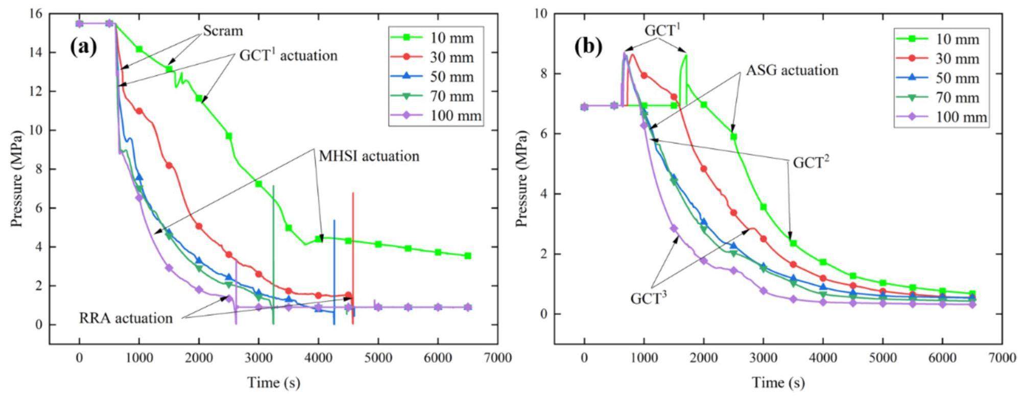
Under accident conditions with a break diameter of 10 mm, the pressure in the primary circuit decreases slowly, and a long time is required to depressurize before the reactor shutdown is triggered. As the size of the break increases, the system parameters change faster, and each system responds earlier.
Figures 4–5 show the fluid temperatures at the core inlet and outlet, fluid temperature at the second side of the SG, cladding temperature, and core minimum dimensionless liquid content, respectively. After core shutdown, the reactor system mainly uses the GCT and the break as the heat sink to remove heat. At this point, the larger the break, the more heat the primary system loses through the break, and the faster the core fluid temperature decreases. As the injection system is put in place, it further provides a heat trap for the core, resulting in a significant drop in core coolant temperature. When the pressure in the primary circuit is lower than 3.0 MPa and the temperature is lower than 180 ℃, the RRA is put into operation. The coolant is extracted from the second circuit and cooled before being injected into the first and third loops. The investment effect of the RRA is significant and contributes to a rapid decrease in the temperature of the primary circuit. The LHSI follows closely, with the RRA and LHSI providing a stable heat sink for the core. The primary circuit temperature decreases rapidly and enters into the unsaturated state after a short oscillation. Finally, the system enters the long-term cooling stage. As observed from the cladding temperature curve in Fig. 4(d), the core was always in a safe state. As shown in Fig. 4(a), there is still a mixture of gas and liquid phases at the top of the core during the entire process; therefore, the cladding temperature changes at different positions of the active zone are basically the same.
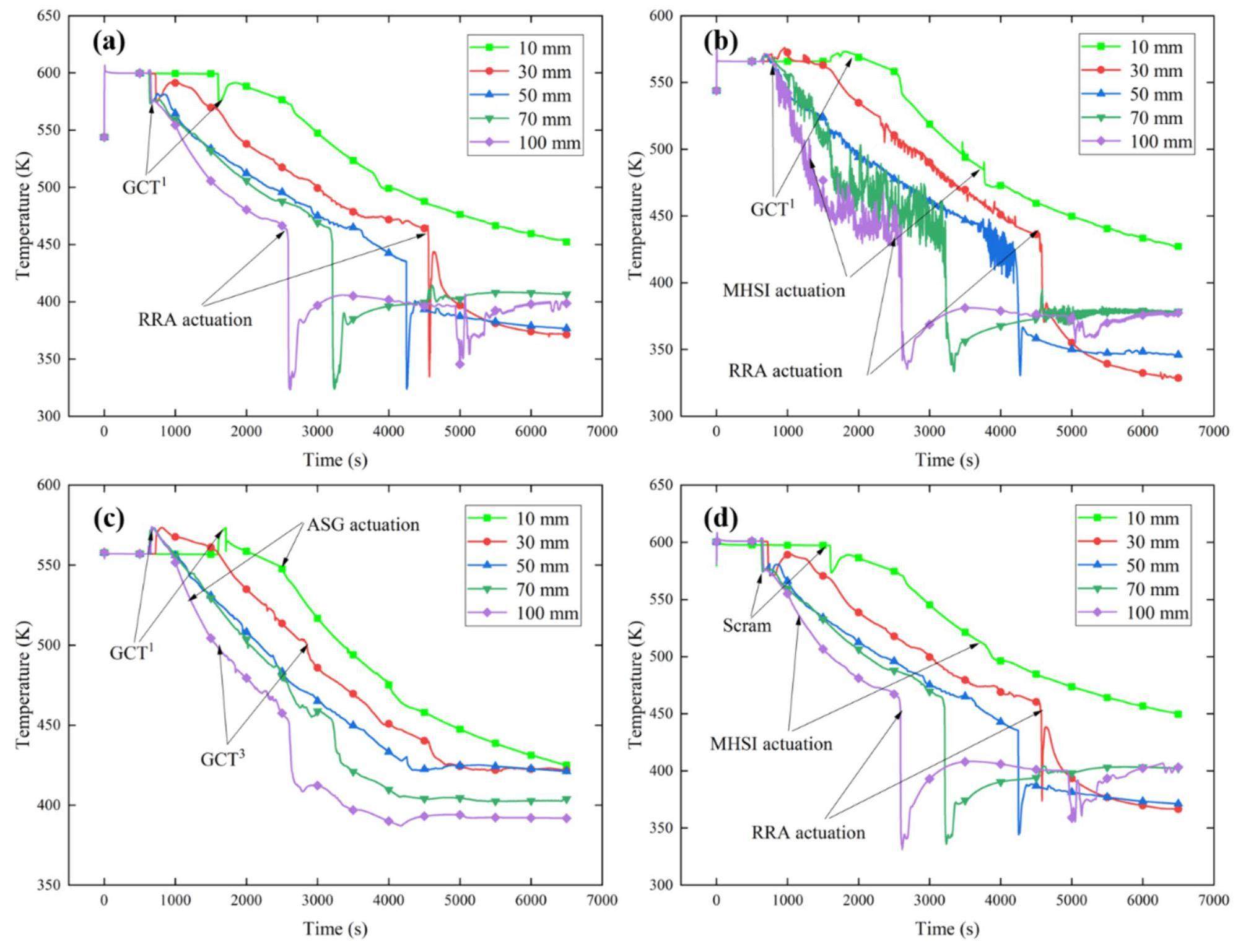
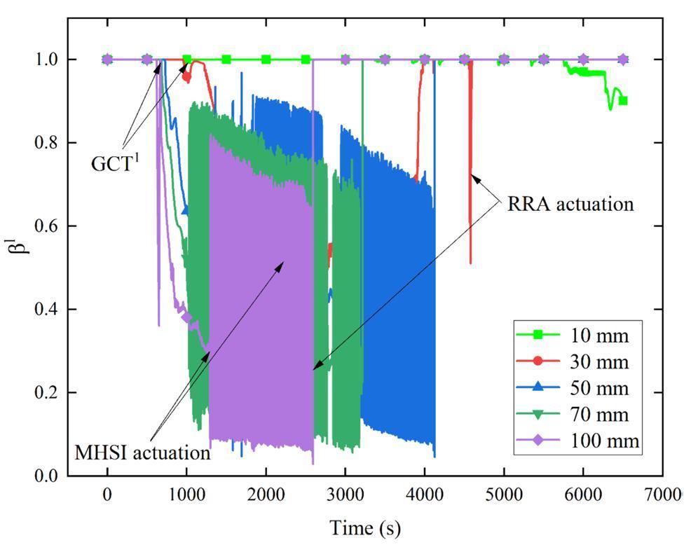
In the accident process, three accident conditions (10, 30, and 50 mm) satisfy that the core cooling rate does not exceed 100 K/h. However, under accident conditions of 70 and 100 mm, owing to the large break, the pressure of the reactor coolant system drops rapidly. More heat is carried away through the break, and the core cannot be cooled at a safe rate. However, no abnormalities are observed in the core-cladding temperature.
Figure 6 shows the transient mass flow rate through the break, reactor core, and GCT. It is known that stopping the main pump causes a rapid drop in the core coolant flow. After the HHSI is operated, the breakout flow decreases because of the pressure drop in the primary circuit. The core coolant flow drops to a smaller value and enters an oscillating state. At this time, the heat-trap demand for the SG is greater in the core. The water in the SG absorbs heat, evaporates, and is rapidly ejected into the atmosphere at a high flow rate through the GCT1. The primary pressure and temperature decrease rapidly, causing the core coolant mass flow rate to be in a state of shock. After the MHSI is operated, the demand of the primary circuit for the second-circuit heat sink is weakened. In rate was reduced to satisfy the requirement of a stable cooling rate for the core. When the RRA and LHSI are operated, the loops oscillate owing to the hot boiling of the newly injected coolant; therefore, the flow rate of GCT3 increases to meet the long-term safety heat discharge requirements.
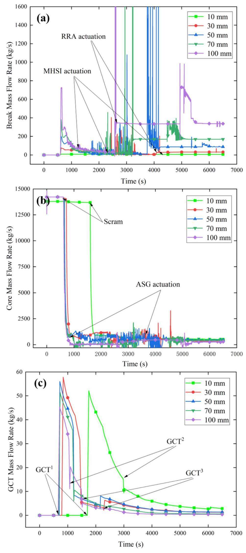
When a break of 10 mm occurs, the loss of coolant in the primary circuit is minimal. Owing to the replenishment of the pressurizer, the coolant mass flow rate does not change during the initial period, and a longer period of pressure drop is required to reach the shutdown condition.
Figure 7 shows the variations in the core, pressurizer, and SG collapsed liquid levels. The pressurizer responds quickly to replenish the water volume in the first loop after the break, ensuring that the core is submerged at the initial stage. When the reactor is shut down, the core collapsed level decreases gradually. When the HHSI is operated, a slight oscillation occurs in the core collapsed liquid level. The opening of the GCT forces the working medium in the SG to evaporate, resulting in a decrease in its water level. Consequently, the heat transfer efficiency of the SG deteriorates. This leads to a decrease in the heat transfer efficiency of the SG and an acceleration in the rate of decrease of the core-collapsed liquid level. Subsequently, the collapsed liquid level in the SG becomes lower than 35%, which triggers an auxiliary feed water (ASG) supply to refill the SG. As shown in Fig. 7(a), the core collapse level exhibited small fluctuations after the auxiliary feedwater was applied. When the MHSI is in operation, the core coolant is replenished, and the core collapsed level decreases at a slower rate. The core collapsed level has dropped to a relative minimum value by the time the LHSI and RRA are put into operation, which is followed by the rapid recovery of the core water level to a flooded state.
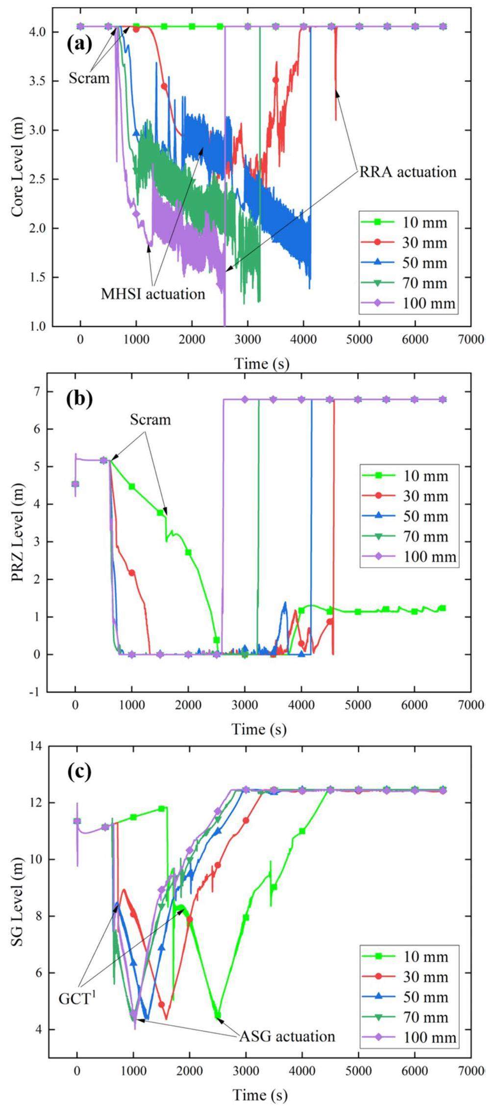
When a break of 10 mm occurs, the liquid level in the pressurizer slowly decreases to replenish the cooling dose lost by the break, and the core remains submerged throughout the process. Under other conditions with break sizes of 30–100 mm, the rate of decrease in the core collapsed liquid level increases with the increase in break size, and the minimum value of the core collapsed liquid level is lower. Accident conditions with larger break sizes trigger the injection and RRA systems earlier, and the core water level rises earlier.
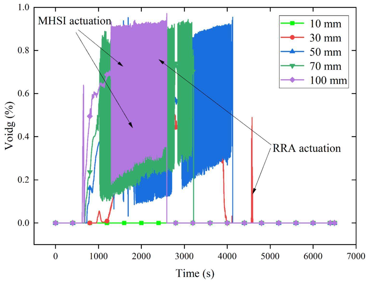
Figure 8 shows the maximum void fraction in the active area of the core. Compared to Fig. 7(a), the void in the active region of the core appears as the core collapsed liquid level gradually decreases. As shown in Figs. 3 and 4(b), the coolant is in a near-saturated state after the start-up of the MHSI, and the core collapsed liquid level decreases. The void fraction at the top of the active zone increases with an increase in the break, which is maintained at approximately 70% under the condition of a 100 mm break. Subsequently, it increases slowly, with an instantaneous maximum of 85%. After the RRA and LHSI are put into operation, the reactor enters the long-term cooling process, and the void in the active area of the core gradually disappears.
For further comparison, the corresponding conditions without GCT input were calculated. Figure 9 shows the pressure in the primary and secondary circuits, core coolant temperature, and core collapsed liquid level. After scrambling, the reactor system releases heat through the break and the SG. Simultaneously, the temperature and pressure of the primary circuit decrease normally, whereas those of the second circuit rapidly increase. Because of the lack of a GCT in the second circuit, the second circuit cannot act as a heat trap when the temperature and pressure increase to a certain value. At this time, the primary circuit cannot release heat into the second circuit through the SG, and the loss of the breakout coolant is the primary method of releasing heat.
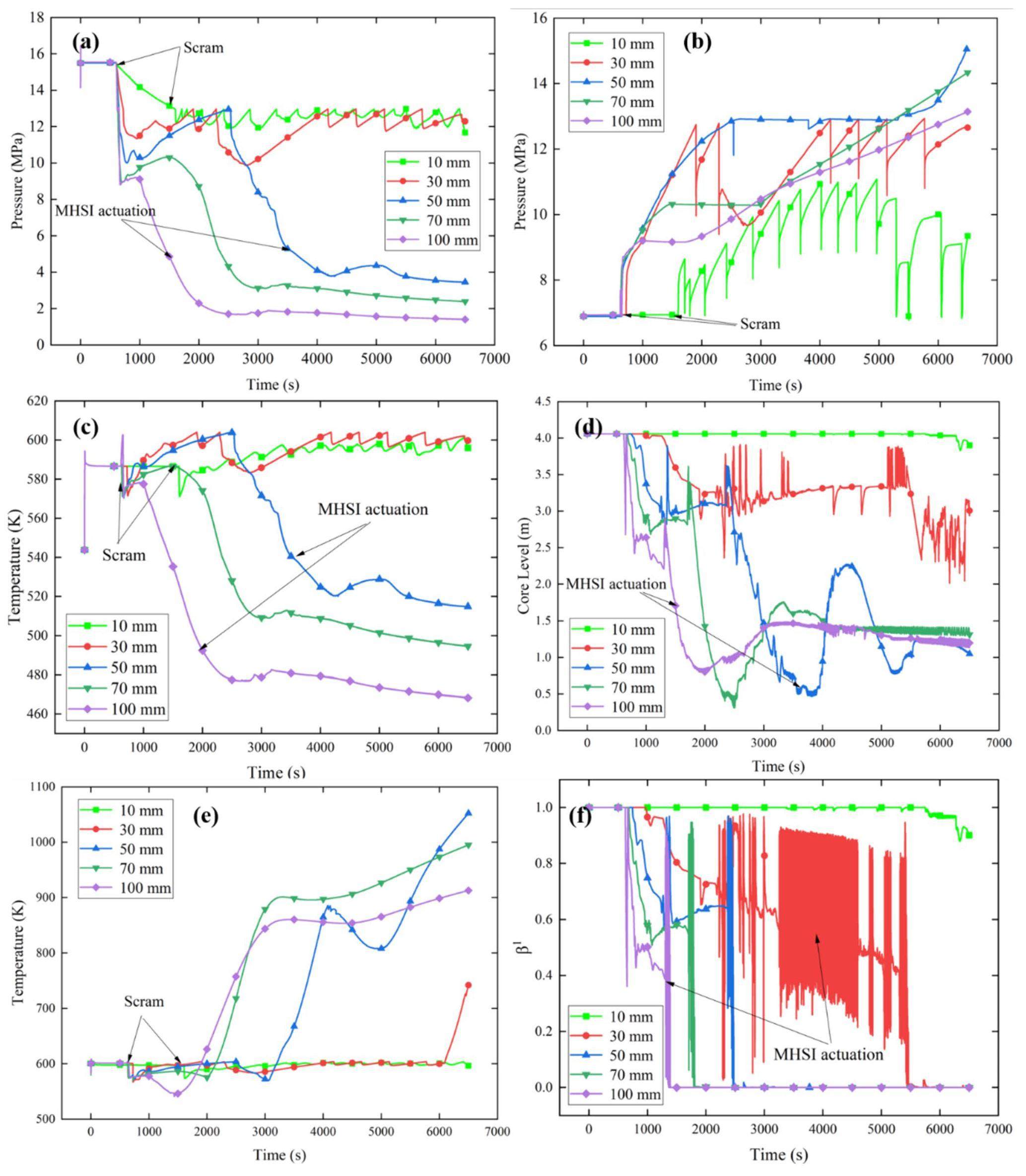
Under small break conditions, the core loses less coolant through the break, and the heat release capacity of the break is limited; thus, the temperature and pressure of the primary circuit can no longer fall after a certain level, and the MHSI and RRA cannot intervene because the trigger conditions are not met, resulting in the system being unable to recharge the coolant to the core for a long period and failing to ensure the safe state of the core. Under the larger break condition, owing to the strong heat release capacity of the break, the middle pressure injection system is triggered at a later stage; thus, the temperature and pressure of the primary circuit continue to drop but fail to reach the conditions of the low-pressure injection system and RRA input. The core is not recharged with the coolant and cannot enter the long-term cooling phase, and at this time the cladding temperature continues to increase. The alloy will react with water vapor when the cladding temperature rises to 820 °C, and will melt when the temperature rises to 1200 °C. Therefore, it is determined that the reactor can maintain the safety of the fuel element temperature below 820 ℃ [33]. It is known from the top (minimum) dimensionless liquid content and envelope temperature of the active zone of the core in Fig. 9(e) and 9(f) that the reactor core is maintained in an unsafe state with high temperature and pressure under the accident condition with a 10 mm break size. Under conditions with 30–100 mm break size, the top of the active zone in the core becomes exposed to different degrees, and the cladding temperature exceeds the safe temperature of the fuel element, which may lead to core melting.
Conclusion
A numerical model of a PWR nuclear power plant was established using the RELAP5 code, and the effects of the GCT on the transient response of the SBLOCA superposed SBO accident were analyzed. The main conclusions are as follows.
1. When the break diameter is less than 50 mm, the GCT is used with the primary safety injection system during the placement process, and the core can be maintained at a safe cooling rate (100 K/h). When the break diameter exceeds 50 mm, the core cooling rate is excessively high; however, the core is not substantially exposed, and the cladding temperature is normal throughout the accident.
2. As the GCT is put into operation, it plays an important role in the initial stage, with a high GCT flow rate to provide sufficient heat traps for the core. After the MHSI is put into operation, the demand for the GCT weakens, and the GCT mass flow rate decreases accordingly. It is recommended that the regulation capacity and response speed of GCT be improved to respond faster in the early stages of an accident.
3. If the GCT is not in operation, the pressure on the shell side of the SG will exceed the limit requirements because of the inability to export heat in a timely manner. Under large break conditions, the release of heat through the break can reduce the core temperature and pressure to different degrees. However, owing to the inability of the safety injection system and RRA to operate, fuel element overheating occurs. Therefore, it is necessary to have a GCT that cooperates with a safety system for cooling.
Design overview of AP1000 Steam turbine bypass discharge system
. Science & Technology Vision 10, 42-43 (2021). https://doi.org/10.19694/j.cnki.issn2095-2457.2021.10.12 (in Chinese)Analysis of the steam venting control system in passive nuclear power plant
. Automatic Instrument 37, 60 (2016). https://doi.org/10.16086/j.cnki.issn1000-0380.201610017 (in Chinese)Analyses of steam bypass system of M310 & domestic mainstream reactor types
. Electric Engineering 16, 55 (2020). https://doi.org/10.19768/j.cnki.dgjs.2020.16.023 (in Chinese)Optimization for Setpoints of Steam Generator Water Level Control Systems in Power-uprated YGN 1 & 2 and Kori 3 & 4
. J. Nucl. Sci. Technol. 42, 1067-1076 (2005). https://doi.org/10.1080/18811248.2005.9711059Determination of the optimal steam dump control system set-points after power uprate of Kori 3/4 and Yonggwang 1/2 Units
. In Proceedings of the American Nuclear Society.Research on real-time simulation of steam dump control system in PWR nuclear power plants
. Nucl. Power Eng. 32, 38-44 (2011).Study on dynamics of steam dump system in scram condition of nuclear power plant
. IFAC-Papers OnLine 52, 360-365 (2019). https://doi.org/10.1016/j.ifacol.2019.08.236Effectiveness and adverse effects of in-vessel retention strategies under a postulated SGTR accident of an OPR1000
. J. Nucl. Sci. Technol. 54, 337-347 (2017). https://doi.org/10.1080/00223131.2016.1273145Design and optimization of control logic of steam discharge system in nuclear power plan
. Electrical Engineering Technology (EET) 22, 22-23 (2020). https://doi.org/10.19768/j.cnki.dgjs.2020.22.009 (in Chinese)Analysis of the IAEA SPE-4 small-break LOCA experiment with RELAP5, TRACE and APROS system codes
. Nucl. Eng. Des. 377, 111109 (2021). https://doi.org/10.1016/j.nucengdes.2021.111109Emergency intervention scheme for steam valve feedback fluctuations of turbine bypass discharge system
. Power Safety Technology 23, 48-50 (2021). (in Chinese)Optimization design of the condenser of GCT-c system
. Hubei Electr. Power 35, 46-47 (2011). https://doi.org/10.19308/j.hep.2011.01.020 (in Chinese)Dynamic characteristic analysis of steam bypass exhaust system of steam turbine
. Nuclear Power Engineering 42, 25-28 (2021). https://doi.org/10.13832/j.jnpe.2021.S2.0025 (in Chinese)Response and fault treatment of GCT system under transient condition
. Science and Technology Vision 01, 359-360 (2017). https://doi.org/10.19694/j.cnki.issn2095-2457.2017.01.267 (in Chinese)Bypass valves and steam dump control system in AP1000 steam turbines
. Therm. Turbine 45, 232-236 (2016). https://doi.org/10.13707/j.cnki.31-1922/th.2016.03.012 (in Chinese)Operation analysis of steam turbine bypass system in AP1000 nuclear power plant
. Mechanical and Electronic Information 15, 162-163 (2011). https://doi.org/10.19514/j.cnki.cn32-1628/tm.2011.15.103 (in Chinese)Analysis of AP1000 steam bypass control
. Science and Technology Innovation and Application 35, 40-41 (2016). (in Chinese)AP1000 turbine bypass valves and steam dump control system
. Dongfang Turbine 01, 27-31 (2017). https://doi.org/10.13808/j.cnki.issn1674-9987.2017.01.006 (in Chinese)Analysis of steam emission control for passive reactors
. Science and Technology Innovation Herald 12, 62-63 (2015). https://doi.org/10.16660/j.cnki.1674-098x.2015.14.059 (in Chinese)Design of atmospheric steam dump system(TSA)atmosphere steam dump valves 30 minutes nonintervention automatic control
. Industrial Instrumentation and Automation Equipment 06, 35-38 (2020). (in Chinese)Response characteristics of HPR1000 primary circuit under different working conditions of the atmospheric relief system after SBLOCA
. Nucl. Eng. Des. 314, 307-317 (2017). https://doi.org/10.1016/j.nucengdes.2017.01.027An analysis on the consequences of a severe accident initiated steam generator tube rupture
. Nucl. Eng. Des. 348, 14-23 (2019). https://doi.org/10.1016/j.nucengdes.2019.04.001Strategy Analysis of Beyond Design Basis Accident for Typical 1000 MWe NPPs
. Nuclear Power Engineering 38, 154-157 (2017). https://doi.org/10.13832/j.jnpe.2017.03.0154Analysis of AP1000 turbine bypass control function
.//Load following dynamic characteristic analysis of casing once-through steam generator
. Atomic Energy Science and Technology 44, 175-182 (2010). (in Chinese)Investigation on two-phase flow instability in parallel channels based on RELAP5 Code
. Atomic Energy Science and Technology 44, 694-700 (2010). (in Chinese)Investigation on Natural Circulation Flow Instability in Single Channel Based on RELAP5 Code
. Atomic Energy Science and Technology 44, 958-963 (2010). (in Chinese)An analytical investigation of loop seal clearings for the SBLOCA tests
. Ann. Nucl. Energy 68, 30-42 (2014). https://doi.org/10.1016/j.anucene.2014.01.003ROSA/LSTF test and RELAP5 analyses on PWR cold leg small-break LOCA with accident management measure and PKL counterpart test
. Nucl. Eng. Technol. 49, 928-940 (2017). https://doi.org/10.1016/j.net.2017.03.004Study on coupling characteristics of small break LOCA in advanced PWR
. Nuclear Power Engineering 41, 189-192 (2020). https://doi.org/10.13832/j.jnpe.2020.02.0189 (in Chinese)Current research on failure criteria of zirconium alloy cladding embrittlement
. Science & Technology Vision 09, 5-10 (2022). https://doi.org/10.19694/j.cnki.issn2095-2457.2022.09.01 (in Chinese)The authors declare that they have no competing interests.

