Introduction
With the development of highly brilliant X-ray sources [1, 2], fast frame-rate detectors [3, 4], and novel sample delivery techniques [5-10], white-beam Laue microdiffraction has attracted considerable interest. In this report, a Laue microdiffraction beamline (BL03HB) supported by the Shanghai Synchrotron Radiation Facility (SSRF) Phase II beamline project, dedicated to both protein crystallography and materials science, is introduced.
White-beam Laue microdiffraction has been extensively used to determine the structure of protein crystals [11-15]. The primary advantages of this method are as follows: 1. The crystal structure can be determined from only a few images of the diffraction data [16]; 2. The measurements can be performed at room temperature [17]; and 3. Data collection is almost instantaneous, allowing the time-resolved investigation of structural changes under physiological conditions [18]. Although several crystallographic beamlines have been built using monochromatic beams [19-23], reports on the construction of Laue crystallography beamlines are rare. Considerable past efforts have focused on enhancing the X-ray flux for the time-resolved structural analysis of proteins. A pink beam with a relative photon flux approximately 100 times greater than that of a monochromatic beam was produced at the BioCARS beamline of the Advanced Photon Source (APS), which reduced the exposure time for X-ray diffraction measurements to approximately 100 ps [24]. This beamline allowed the investigation of several reversible photoinduced structural changes triggered by laser pulses [24]. Diffraction experiments conducted under nitrogen flow at 100 K could potentially damage the crystals duringharvesting and freezing [5-10]. Therefore, there is increasing demand to investigate the crystallography of biological macromolecules at room temperature [25-31]. With developments in Laue microdiffraction technology, the flux density has further enhanced and the beam size has become smaller. This should be applied to Laue crystallography beamlines for in situ room-temperature microdiffraction experiments.
Further, white-beam Laue microdiffraction has been widely applied to characterize the distributions of local crystal structures including lattice parameters, orientations, grain boundaries, and strain in various materials [32-34]. Using a microbeam with synchrotron light sources, Laue microdiffraction can be used to easily map the local microstructural distributions of large samples. This high-throughput and nondestructive technique is known for its fast data acquisition, high sensitivity, and high spatial resolution and is especially suitable for in situ experiments in materials science. X-ray fluorescence (XRF) spectra are often collected simultaneously to obtain local elemental and chemical information.
Herein, we report on a white-beam Laue microdiffraction beamline, BL03HB, commissioned at SSRF in June 2023. As part of the SSRF Phase II project launched in December 2016, this beamline is based on a superbend dipole magnet as its light source, with a two-stage focusing system to achieve an X-ray microbeam. Two sets of switchable microfocusing KB mirrors were installed to deliver the focused beam to two different experimental sectors at the experimental end station. The first is for protein crystallography, and the second for materials science. In the protein crystallography sector, the white-beam Laue diffraction from protein crystals is collected using a Pilatus 2M area detector to capture snapshots of the transmission geometry. The samples on crystalline plates can be measured at room temperature. In the materials science sector, white-beam Laue diffraction is collected in a reflection geometry from the surface of samples using another Pilatus 2M area detector during the scanning of samples.
Beamline
Light source
A superbend dipole magnet with a magnetic field of 2.29 T was adopted as the light source of the BL03HB beamline, which is often used for its high flux, large energy range, good spectral continuity, and low heat load.
Optical layout
Figure 1 presents the optical layout of this beamline with its first water-cooled white-beam slit located 18 m from the light source. Subsequently, a toroidal mirror is vertically installed at 20 m with a horizontal focusing ratio of 20:16, followed by a four-bounce monochromator at 23 m and a second focusing mirror at 26 m with a vertical focusing ratio of 2:1. A second water-cooled white-beam slit is installed 36 m from the light source to define the size of the secondary light source.
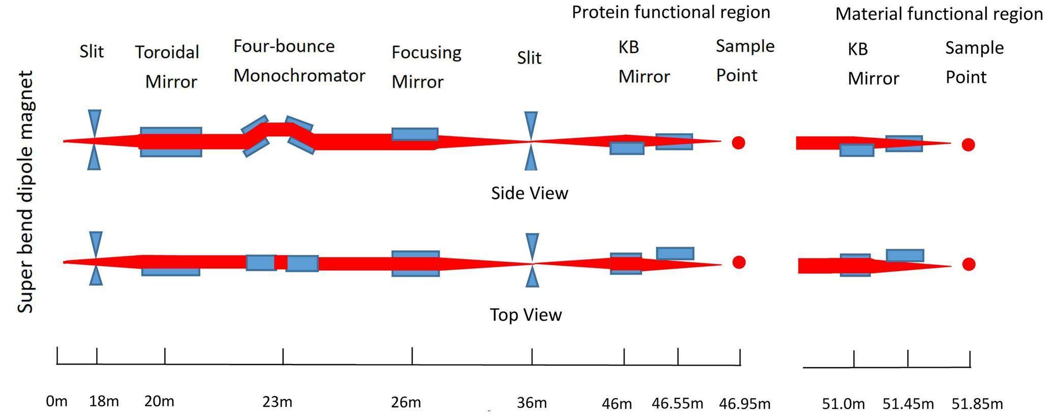
The four-bounce monochromator consisting of two channel-cut Si(111) crystals mounted on two precision goniometers transmits monochromatic X-rays with different energies by simultaneously rotating the two crystals to the corresponding Bragg angle, mirror-symmetrically with respect to the plane vertical to the beam path. When both crystals are aligned parallel to the optical path, the white beam passes directly through the openings of the two channel-cut crystals. Thus, this monochromator can deliver monochromatic X-rays and a white beam along the same path as the monochromator by simply rotating the two channel-cut crystals.
After the slit for the secondary light source, the first set of Kirkpatrick–Baez (K-B) mirrors (FMB Oxford Ltd.) at 46 m is used to focus the X-rays from the secondary light source to the protein crystallography experimental sector. Using the first horizontally placed mirror (length 60 cm) to focus the beam vertically and the second vertically placed mirror (length 40 cm) to focus the beam horizontally, a white microbeam with a size of 4.2 μm×4.3 μm can be achieved. By adjusting the widths of the slit for the secondary light source in both directions, the focused beam size can be flexibly tuned. Because Pt was chosen as the coating for both K-B mirrors with an incident angle of 3.5 mrad, this relatively large angle favors a high flux with a cutoff energy of 20 keV. The photon energy range for the protein crystallography experimental sector is approximately 7–20 keV. A flux of 1.95×10¹⁰ phs/s at an energy of 10 keV can be achieved with a storage ring current of 300 mA.
The first set of K-B mirrors can be moved out of the optical path, and the beam can then be transmitted to the second set of K-B mirrors at 51 m. These two K-B mirrors with a length of 40 cm are used to focus the white beam with a spot size of 0.9 μm×1.3 μm at 51.85 m in the materials science sector. Similarly, for the first set of KB mirrors, the spot size can be adjusted by tunning the size of the slit for the secondary light source. The second set of K-B mirrors are also coated with Pt, but with an incident angle of 2.6 mrad, thus a higher cutoff energy of 30 keV is achieved in the materials science sector with a photon energy range of approximately 7–30 keV. A flux of 1.1×10⁹ phs/s at an energy of 10 keV can be achieved with a storage ring current of 300 mA.
Specifications of the beamline
The BL03HB beamline was commissioned in June, 2023. The specifications for a storage ring current of 300 mA, converted from the measured values during commission, are listed in Table 1. The flux and energy range of the white beam in Table 1 are design specifications.
| Protein crystallography sector | Materials science sector | |
|---|---|---|
| Energy range | 6.538-20 keV (monochromatic) | 6.538-20 keV (monochromatic) |
| 7-20 keV (white beam) | 7-30 keV (white beam) | |
| Energy resolution | 0.96×10⁻⁴@10 keV | 0.96×10⁻⁴@10 keV |
| Photon flux | ~1.95×10¹⁰ phs/s @10 keV (monochromatic) | ~1.11×10⁹ phs/s @10 keV (monochromatic) |
| ~6×10¹⁴ phs/s (white beam) | ~6×10¹⁴ phs/s (white beam) | |
| Beam size | 4.0 μm×4.2 μm2@10 keV (monochromatic) | 0.8 μm×1.4 μm2@10 keV (monochromatic) |
| 4.2 μm×4.3 μm2 (white beam) | 0.9 μm×1.3 μm2 (white beam) |
Experimental station
The experimental station is separated into two sectors: one dedicated to protein crystallography and the other to materials science. A schematic 3D drawing of the experimental station is shown in Fig. 2.
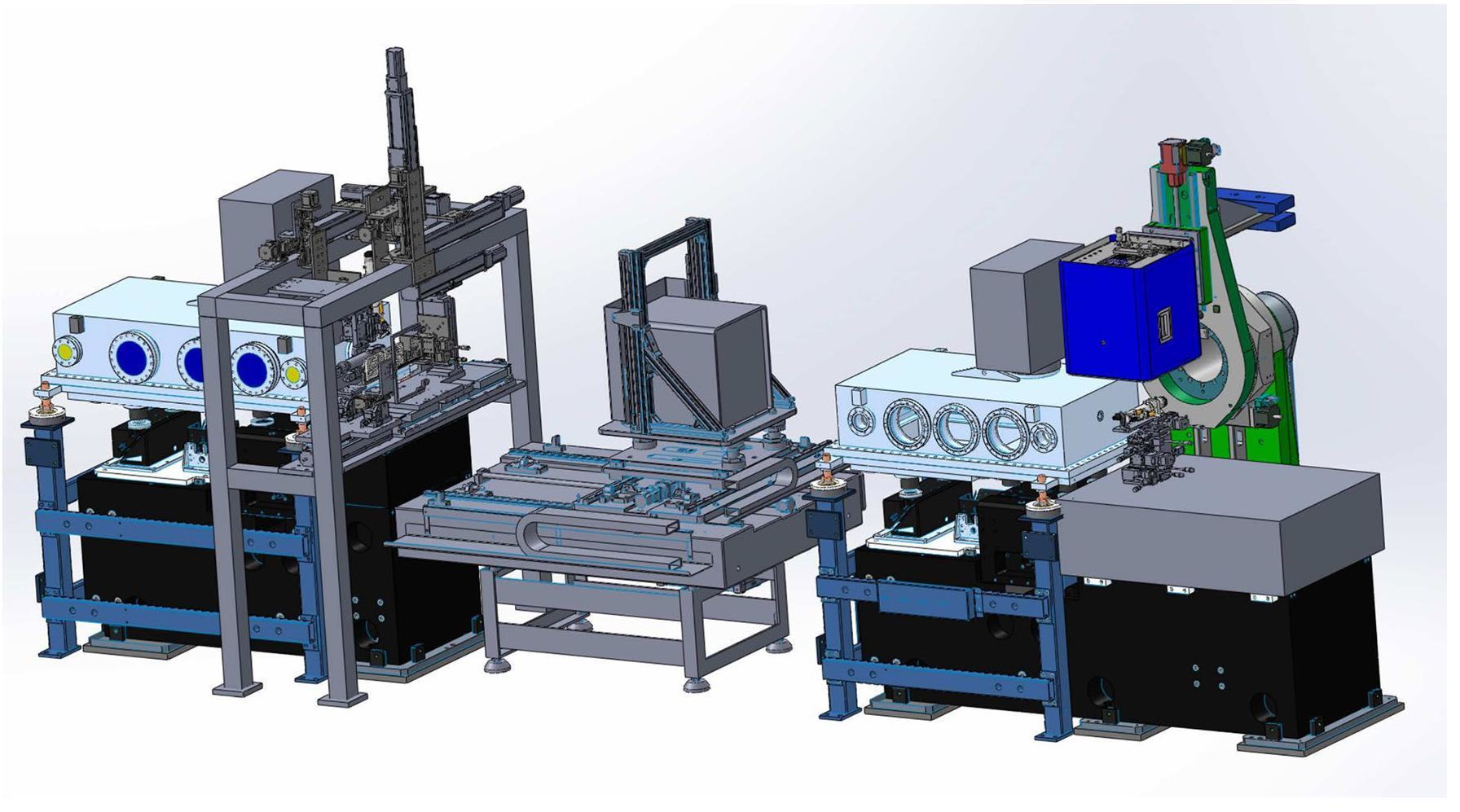
Shown in the center of Fig. 2, a Pilatus 2M detector in the protein crystallography sector is mounted on a platform with two translational degrees (X,Y) of freedom to move the detector around sample point. At the end of the vacuum chamber of the first K–B mirror and before the Pilatus 2M detector, on the left of Fig. 2 is a homemade diffractometer with a frame for installing various instruments, which will be discussed later. All instruments, including the detector in the protein crystallography sector, must move out of the X-ray light path, and a vacuum pipe is set up between the two K–B mirror chambers directly when the materials science sector is in operation. On the right of Fig. 2, an optical platform is used to support the stage for the samples in the materials science sector. On top of this stage is the Pilatus 2M detector, mounted on the arm of a rotation stage. Further details of the two experimental sectors are provided below.
Protein crystallography sector
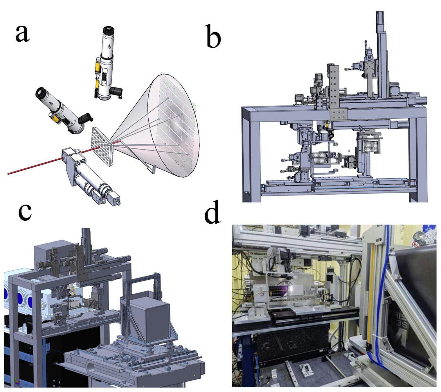
In the protein crystallography sector, Laue microdiffraction from protein crystals is measured in transmission geometry. A homemade in situ diffractometer was developed that allows the measurement of samples on crystal plates, as shown in Fig. 3. Consisting of a frame on which various instruments are mounted for the measurements of samples on crystal plates, the Laue diffractometer is located behind the K-B mirrors and before the area detector, as shown in Fig. 3c. The 4D translation sample stage, illustrated in Fig. 4A, can load the crystal plates and adjust their positions to allow the X-ray beam to be incident on different samples for the measurements. As illustrated in Fig. 3a and shown in Fig. 4(B-D), three microscopes are mounted on different sides to visually identify the crystal samples on the crystal plate. One microscope is mounted on a 3D translation stage and positioned perpendicular to the beam path. It features a planar optical mirror in front of the microscope, set at a 45 angle to both the beam path and the microscope itself. The reflective side of the mirror faces the sample, facilitating visualization of the sample images through the microscope. Simultaneously, the mirror incorporates an aperture with a diameter of 2 mm, allowing the X-rays to pass through and reach the samples after fine adjustments to the position of the mirror relative to the beam path. This setup, referred to as an on-axis-view microscope, serves to guide the adjustment of samples to the center of the field of view where X-rays are present.
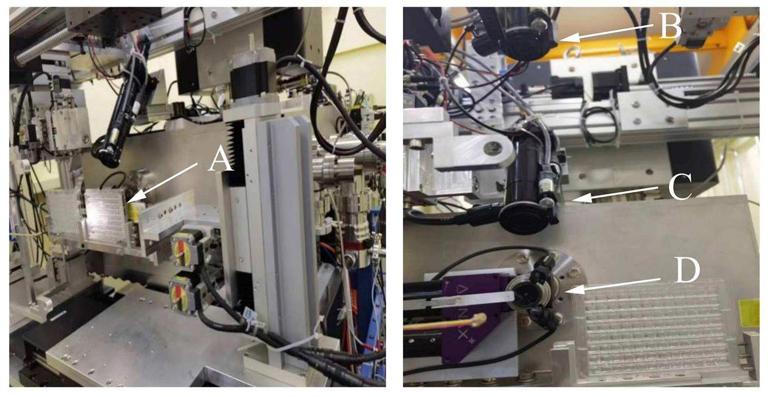
Additionally, an active beamstop [35] with an outer diameter of 4 mm is installed 80 mm from the sample point. Simultaneously, a photodiode is mounted on the beamstop to monitor the beam intensity, and its readout is collected using a picoammeter (model 6482). From the readout of the photodiode at different positions with respect to the beam position, the beamstop can be adjusted to the center of the beam. A collimator made of a pinhole with an inner diameter of 0.3 mm is used during measurements. The crystal plate shown in Fig. 4 consists of 96 wells, and multipoint in situ data collection from any one crystal sample within these wells can be achieved if the crystal is larger than the beam size of 4.2 μm×4.3 μm. While data collection is almost instant and does not involve sample rotation, it is suitable for time-resolved in situ experiments using the pump-probe technique.
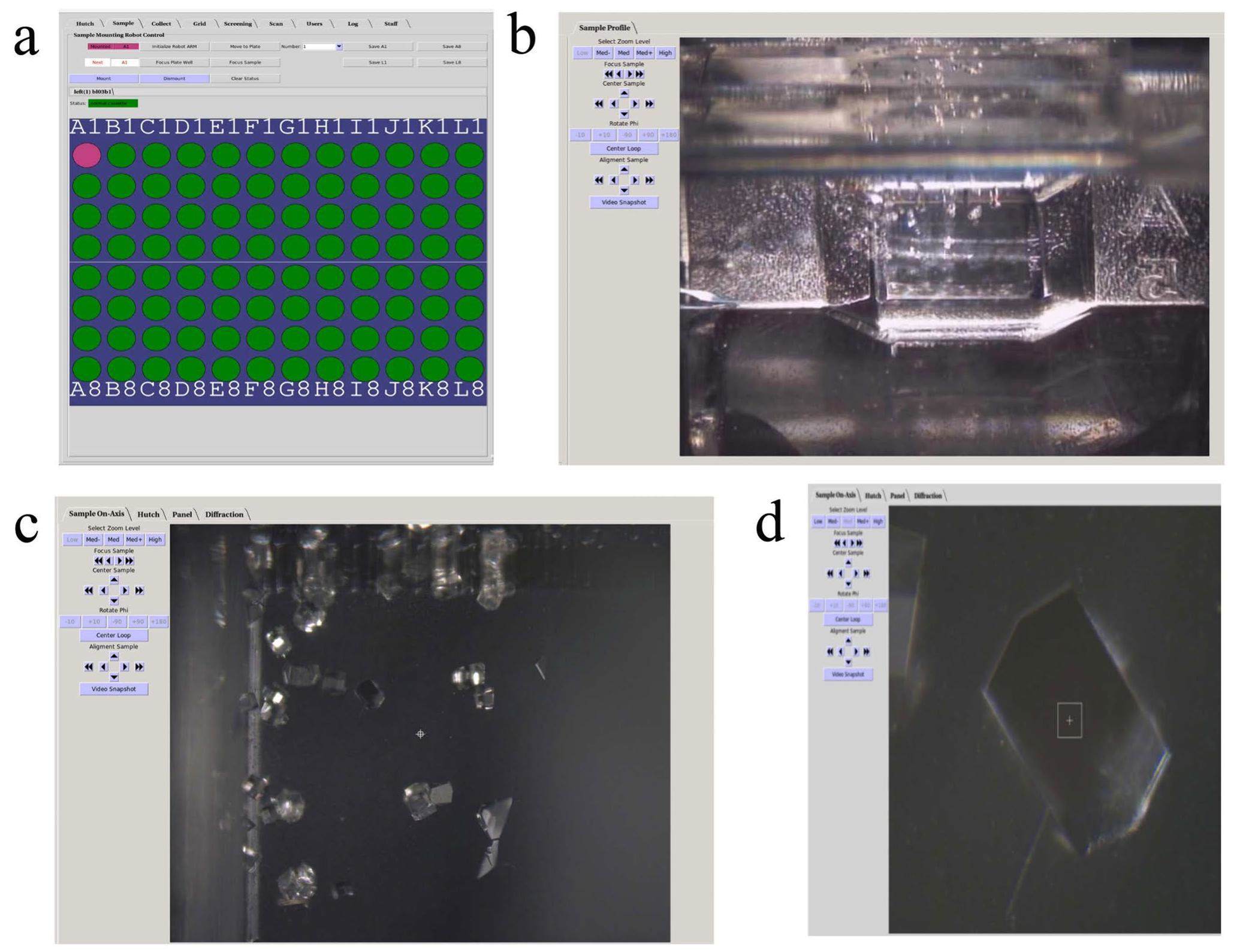
To move the crystal plate to allow the X-ray beam to be incident on different crystal samples for data collection [36], control software based on BluIce [37] is used, with its user operating software interface shown in Fig. 5. It is used for switching between different wells represented by the green or pink discs of the crystal plate in Fig. 5a, after saving the positional information of the four corner wells, the position of each well can be calculated. Thus, the center of the individual well can be quickly moved to the beam position using the mount function in the BluIce software. Figure 5b presents an image of a well viewed using microscope C (see Fig. 4) after one well is moves to the beam position, where tiny crystals are visible on the image. By moving the cursor to a chosen point in this image and clicking, the sample is automatically aligned with this point to the beam position. Using the on-axis-view microscope shown in Fig. 5c, any crystal in the scope can be selected using the cursor, and with a click this crystal is aligned with the beam position automatically. Figure 5d shows an enlarged image of a selected crystal in the center view using the same on-axis-view microscope after magnification. The white rectangle at the center of the image in Fig. 5d marks the beam position on the crystal, and the same software can be used to collect diffraction data from this position.
To collect data with minimal radiation damage, various scanning strategies for the samples during measurements can be utilized with the present control software. The data can be collected from an area with rectangles or ellipses of different sizes, and the scanning route can be linear or polygonal. Moreover, the present setup allows the crystal plate to be rotated by a few angles for data collection from the same sample, which enhances the completeness of the diffraction data.
Material science sector
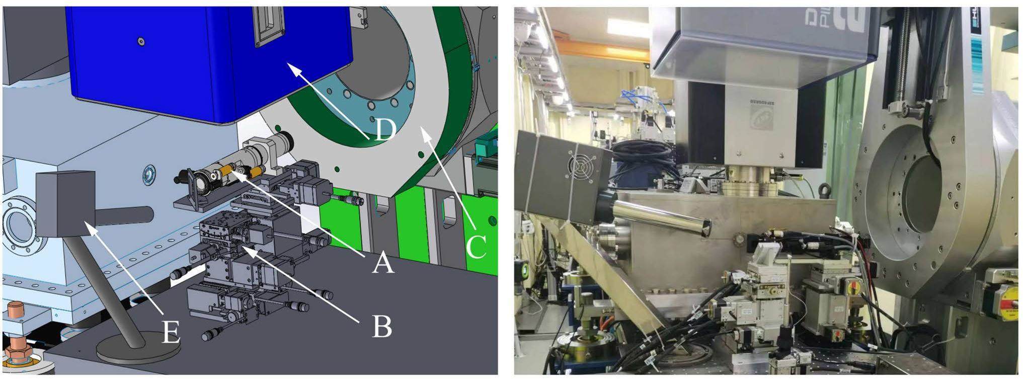
A close-up view of the 3D drawing of the materials science experimental sector around the sample stage is shown on the left of Fig. 6. A photograph of the experimental sector in the same area is shown on the right side of the figure. In this sector, an on-axis-view microscope, similar to that in the protein crystallography experimental sector, was mounted on a 3D translation stage behind the K-B mirrors. After this microscope, the sample stage offers six degrees of freedom: three rotational motions (pitch, yaw, and roll), and three translational movements (X, Y, Z); thus, the precise positioning and orientation of the sample during the experiments can be well manipulated. The Pilatus 2M detector was installed on the arm of a one-circle diffractometer (HUBER, Ltd.). This arrangement allows the detector to be mounted vertically over the samples, as illustrated in Fig. 6, thereby enabling the detection of diffraction signals from the sample surface at approximately 45 to the beam path. Alternatively, the detector can be rotated perpendicular to the beam path, facilitating transmission or grazing-incidence geometry for specific experimental configurations. This versatile setup provides flexibility for acquiring diffraction data under various geometrical conditions. In addition, a four-element fluorescence detector is installed in this sector. During X-ray diffraction experiments, full-energy fluorescence spectra are obtained simultaneously using this fluorescence detector. The use of a microbeam in this sector allows the application of both X-ray diffraction and X-ray fluorescence techniques to map the sample surface. This is achieved by scanning the sample with respect to the microbeam. The scanning process enables the collection of spatially resolved information, offering insights into the crystallographic and elemental composition variations across the surface of the sample. The control of the data acquisition software is based on BluIce and a locally developed MATLAB-based program, which can be easily modified according to the different demands of the experiments.
Calibration of the experimental geometry
Calibration of the experimental geometry in the protein crystallography experimental sector is as follows: YAG (yttrium aluminum garnet) crystals are placed on the sample stage. The YAG sample is then moved to the focal plane of the microscope. Subsequently, the exposure time of the detector is set as 0.1 s and the diffraction data are collected from the YAG sample using the white beam. To enlarge the angular range of the data collection as much as possible, the detector can be moved horizontally to different positions. The diffraction data from all positions are then merged into a single 2D diffraction pattern, and the merged YAG diffraction pattern and experimental geometry can be calibrated.
The calibration of the experimental geometry in the materials science experimental sector is as follows: A Si(111) sample is placed on the sample stage at 45° to the beam path, and the area detector is placed perpendicular to the sample. The exposure time of the detector is set as 0.1 s and the diffraction pattern of Si(111) is collected using the white beam. From the 2D data, the experimental geometry of all the pixels of the detector with respect to the sample can be determined.
Data analysis
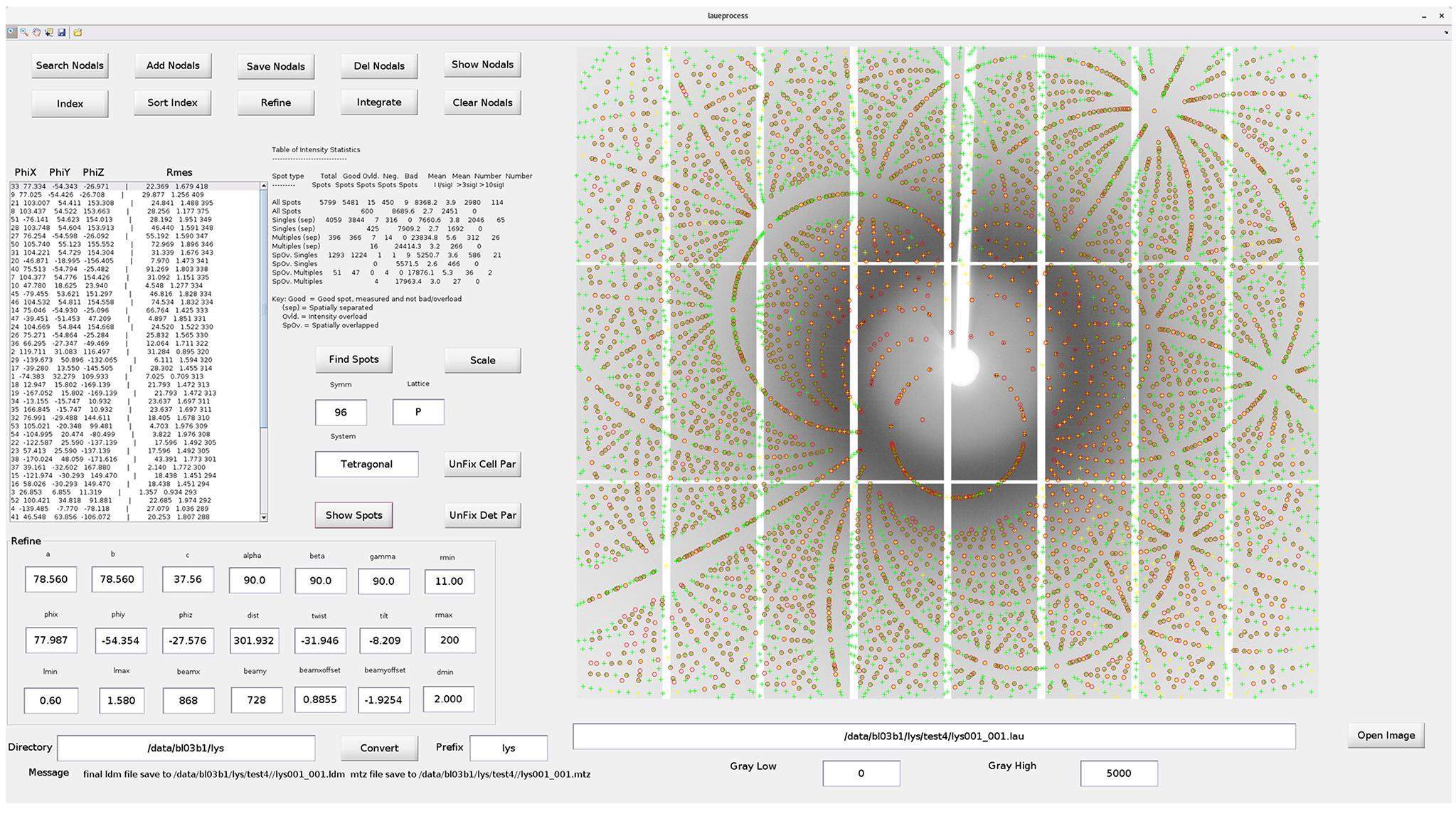
Although several software packages are available for analyzing the data from monochromatic beams [38], data analysis software packages for Laue crystallography are rare. Based on the Lauegen [39, 40] software, a locally developed program, Laueprocess, is used for analyzing the collected Laue diffraction patterns for protein crystals (Fig. 7). Prior to using this software, knowledge of the cell parameters and space groups of the measured crystals is necessary. Therefore, nodals for several crystal planes must be selected manually to index the measured diffraction pattern. After the orientation of the crystal is determined, the structural parameters can be refined by indexing the pattern being finalized. At this stage, the intensity of each diffraction spot can be integrated from the measured pattern for structure refinement, which is performed using the PHENIX program package (https://phenix-online.org/). The final resolution is defined as the highest resolution shell completeness of at least 25%. In addition, Laueprocess has also been successfully used to analyze the structure of inorganic single crystals, such as metal–organic frameworks, from their measured Laue diffraction data at the BL03HB beamline.
To analyze white-beam Laue diffraction data from the materials science experimental sector, software packages such as XMAS at Advanced Light Source, LaueGo at Advanced Photon Source, and LaueTools (https://github.com/BM32ESRF/lauetools) are available. To make data analysis more efficient, software based on Python is currently under development at the BL03HB beamline.
First commissioning results
Laue diffraction data from standard samples
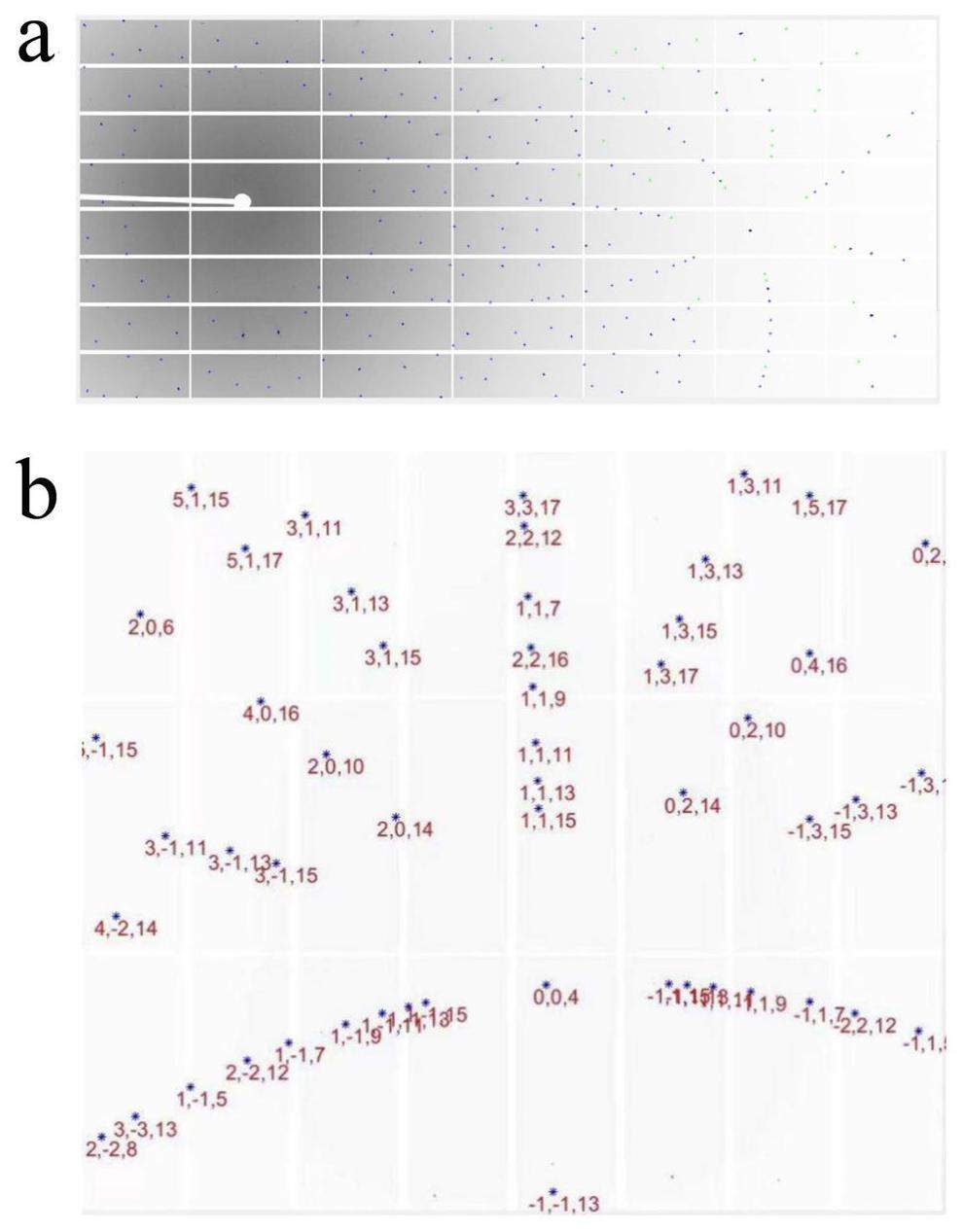
Figure 8 shows a white-beam Laue diffraction image from a YAG sample, which was merged with the data collected by the area detector at three different positions during the first commission in the protein crystallography experimental sector. As mentioned previously, the YAG sample is often used to calibrate the experimental geometry, including the beam position and detector distance. Based on the data shown in Fig. 8a, the derived experimental geometric and lattice parameters of the YAG sample are listed in Table 2.
| Parameters | Value |
|---|---|
| Phix (°) | 44.56 |
| Phiy (°) | -3.98 |
| Phiz (°) | 58.94 |
| Beam_x | 868 pixel |
| Beam_y | 732 pixel |
| Detector distance (mm) | 259.82 |
| System | Cubic |
| Lattice | I |
| Cell (a, b, c) (Å) | 12.01, 12.01, 12.01 |
| α, β, γ (°) | 90, 90, 90 |
Figure 8a shows a white-beam Laue diffraction pattern from a Si(111) sample measured in the materials science sector. Data were collected at an incidence angle of 45 and the detector was placed perpendicularly. All the diffraction spots are indexed in Fig. 8b. The geometry of the materials science experimental sector was calibrated based on the present data.
Crystal structure of Lysozyme
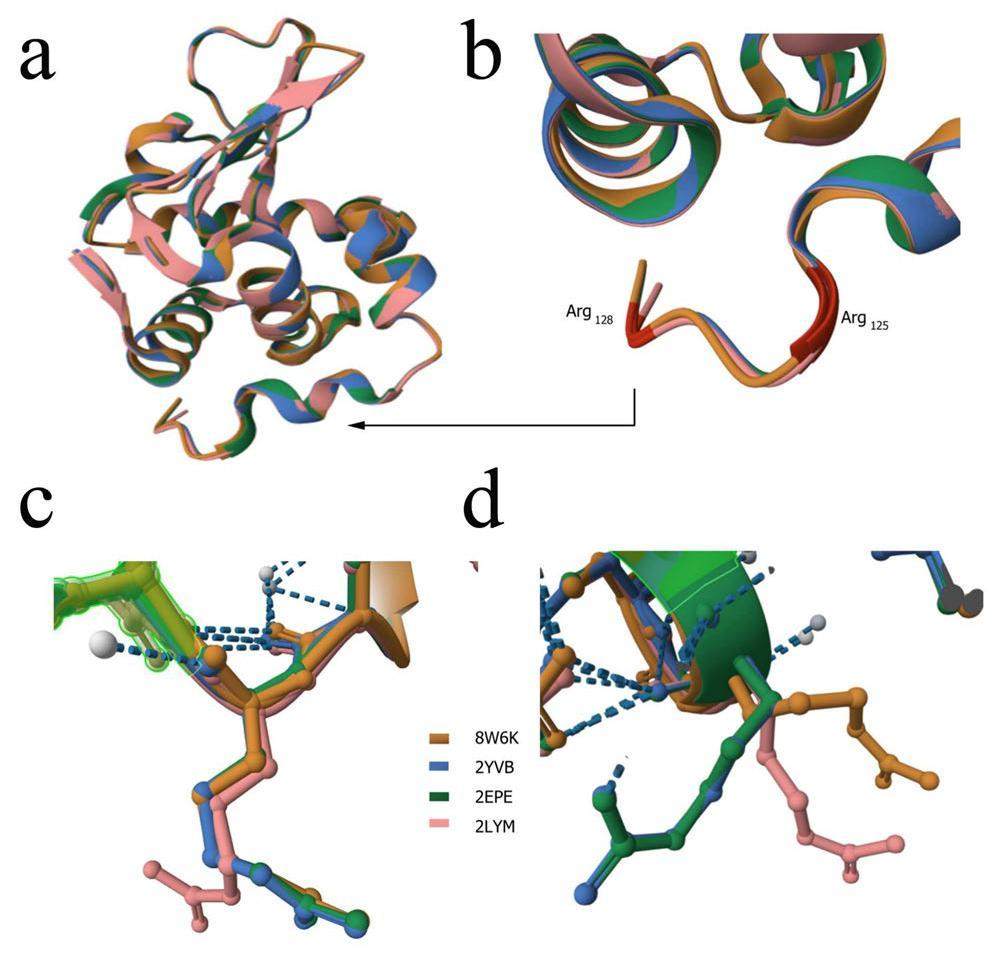
The Lysozyme structure (PDB: 8W6K, yellow, this study), as determined by our in situ room-temperature Laue diffraction method, was compared with crystal growth at 1000 atm (2LYM, pink, from the PDB database) and crystal growth using the capillary method (2EPE, green; 2YVB, blue, from the PDB database). Our results show that the changes were small on average (Fig. 9a). The thermal motion of atoms at room temperature in Lysozyme crystals results in fluctuations and produces small changes owing to shifts in covalently bonded atoms through bond stretching or angle bending. Furthermore, we found a structural difference at the end of chain A (Fig. 9a). Structural differences were mainly observed at residues Arg125 and Arg128 (marked in brown) (Fig. 9b). The residue structure of Arg128 was compared, and the results show that Arg128 of 2LYM was significantly shifted compared to that of 8W6K, 2EPE, 2YVB (Fig. 9c). The residue structure of Arg125 was also analyzed; Arg125 of 8W6K and 2LYM was significantly shifted compared to that of 2EPE and 2YVB (Fig. 9d). The structural discrepancy between Arg125 of 8W6K and Arg125 of 2EPE or 2YVB is speculated to result from the in situ room-temperature Laue diffraction method. Our data collection strategy may affect the salt bridge of Arg125 and drive Arg125 to a new position associated with Lysozyme activity. The motion of the residue Arg125 of Lysozyme at room temperature using the in situ Laue diffraction method will be analyzed in the future.
Summary and conclusion
The BL03HB beamline was constructed at SSRF with sectors dedicated to protein crystallography and materials science applications. This report provides a technical description of the main components of both the beamline and end station. In the first experimental sector, white-beam Laue microdiffraction with a beam spot of 4.2 μm×4.3 μm was applied to determine the structure of the protein crystals from only a few images of diffraction data collected at room temperature. The first commission results demonstrated a structural resolution of 2.0 Å for Lysozme. In the materials science sector, white-beam Laue diffraction with a beam spot of 0.9 μm×1.3 μm is collected in a reflection geometry, which can be used to map the local microstructural distribution on the sample surface, including the crystal orientation and strain. The beamline was commissioned in June 2023, followed by a pilot run for about half a year. In January 2024, it officially opened to users. As a beamline dedicated to white-beam Laue diffraction, the BL03HB beamline significantly impacts both protein crystallography and materials science, especially for the time-resolved study of crystal structures.
Physics design of the HEPS LINAC
. Radiat. Detect. Technol. Methods 4, 497-506 (2020). https://doi.org/10.1007/s41605-020-00205-wThe physics design of HEPS Linac bunching system
. Radiat. Detect. Technol. Methods 4, 433-439 (2020). https://doi.org/10.1007/s41605-020-00200-1HEPS-BPIX2: The hybrid pixel detector upgrade for high energy photon source in China
. Nucl. Instrum. Methods Phys. Res. A 958, 162488 (2019). https://doi.org/10.1016/j.nima.2019.162488Tristan10M detector: characterization of a large area detector for time resolved experiments based on Timepix3 chip
. J. Instrumentation 17, C07019 (2022). https://doi.org/10.1088/1748-0221/17/07/C07019A guide to sample delivery systems for serial crystallography
. FEBS J. 286, 4402-4417 (2019). https://doi.org/10.1111/febs.15099Microfluidic rotating-target device capable of three-degrees-of-freedom motion for efficient in situ serial synchrotron crystallography
. J. Synchrotron Rad. 30, 347-358 (2023). https://doi.org/10.1107/s1600577523000462A novel sample delivery system based on circular motion for in situ serial synchrotron crystallography
. Lab. Chip. 20, 3888-3898 (2020). https://doi.org/10.1039/d0lc00443jNew design for multi-crystal data collection at SSRF
. Nucl. Sci. Tech. 29, 21 (2018). https://doi.org/10.1007/s41365-018-0357-5Microplates for Crystal Growth and in situ Data Collection at a Synchrotron Beamline
. Crystals 10, 798 (2020). https://doi.org/10.3390/cryst10090798Novel combined crystallization plate for high-throughput crystal screening and in situ data collection at a crystallography beamline
. Acta Crystallogr. F Struct. Biol. Commun. 77, 319-327 (2021). https://doi.org/10.1107/s2053230x21008104New methods in time-resolved Laue pump-probe crystallography at synchrotron sources
. J. Synchrotron Rad. 22, 280-287 (2015). https://doi.org/10.1107/S1600577514026538High-resolution crystal structures of a myxobacterial phytochrome at cryo and room temperatures
. Struct. Dyn. 6, 054701 (2019). https://doi.org/10.1063/1.5120527High-viscosity injector-based pink-beam serial crystallography of microcrystals at a synchrotron radiation source
. IUCrJ 6, 412-425 (2019). https://doi.org/10.1107/S205225251900263XIn situ serial Laue diffraction on a microfluidic crystallization device
. J. Appl. Crystallogr. 47, 1975-1982 (2014). https://doi.org/10.1107/S1600576714023322Time-resolved serial crystallography captures high-resolution intermediates of photoactive yellow protein
. Science 346, 1242-1246 (2014). https://doi.org/10.1126/science.1259357Towards time-resolved serial crystallography in a microfluidic device
. Acta Crystallogr. F Struct. Biol. Commun. 71, 823-830 (2015). https://doi.org/10.1107/S2053230X15009061Complementarity of neutron, XFEL and synchrotron crystallography for defining the structures of metalloenzymes at room temperature
. IUCrJ. 9, 610-624 (2022). https://doi.org/10.1107/S2052252522006418Light-induced protein structural dynamics in bacteriophytochrome revealed by time-resolved x-ray solution scattering
. Science Advances 8, eabm6278 (2022). https://doi.org/10.1126/sciadv.abm6278The macromolecular crystallography beamline of SSRF
. Nucl. Sci. Tech. 26, 12-17 (2015). https://doi.org/10.13538/j.1001-8042/nst.26.010102Upgrade of macromolecular crystallography beamline BL17U1 at SSRF
. Nucl. Sci. Tech. 29, 68 (2018). https://doi.org/10.1007/s41365-018-0398-9BL02U1: the relocated macromolecular crystallography beamline at the Shanghai Synchrotron Radiation Facility
. Nucl. Sci. Tech. 34, 193 (2023). https://doi.org/10.1007/s41365-023-01348-3The biosafety level-2 macromolecular crystallography beamline(BL10U2) at the Shanghai Synchrotron Radiation Facility
. Nucl. Sci. Tech. 34, 202 (2023). https://doi.org/10.1007/s41365-023-01350-9Status of the crystallography beamlines at SSRF
. Eur. Phys. J. Plus 130, 32 (2015). https://doi.org/10.1140/epjp/i2015-15032-6Watching a signaling protein function in real time via 100-ps time-resolved Laue crystallography
. Proc. Natl. Acad. Sci. U S A. 109, 19256-19261 (2012). https://doi.org/10.1073/pnas.1210938109An automated platform for in situ serial crystallography at room temperature
. IUCrJ. 7, 1009-1018 (2020). https://doi.org/10.1107/S2052252520011288Crystal-on-crystal chips for in situ serial diffraction at room temperature,Lab
. Chip 18, 2246-2256 (2020). https://doi.org/10.1039/C8LC00489GThe hydrolytic water molecule in trypsin, revealed by time-resolved Laue crystallography
. Science. 259, 669-673 (1993). https://doi.org/10.1126/science.8430314Time-resolved β-lactam cleavage by L1 metallo-β-lactamase
. Nat. Commun. 13, 7379 (2022). https://doi.org/10.1038/s41467-022-35029-3On-chip Crystallization and Large-Scale Serial Diffraction at Room Temperature
. JoVE 181, e63022 (2022). https://doi.org/10.3791/63022Serial Crystallography for Structure-Based Drug Discovery, Trends Pharmacol
. Sci. 41, 830-839 (2020). https://doi.org/10.1016/j.tips.2020.08.009Time-resolved serial femtosecond crystallography on fatty-acid photodecarboxylase: lessons learned
. Acta Crystallogr. D 78, 1131-1142 (2022). https://doi.org/10.1107/S2059798322007525Real-time microstructure imaging by Laue microdiffraction: A sample application in laser 3D printed Ni-based superalloys
, Scientific Reports 6, 28144 (2016). https://doi.org/10.1038/srep28144Development of micro-Laue technique at Shanghai Synchrotron Radiation Facility for materials sciences
, Science China Materials, 64, 2348-2358 (2021). https://doi.org/10.1007/s40843-021-1648-3Scanning X-ray microdiffraction with submicrometer white beam for strain/stress and orientation mapping in thin films
. J. Synchrotron Rad. 10, 137-143 (2003). https://doi.org/10.1107/S0909049502021362An active beamstop for accurate measurement of high intensity X-ray beams
. Nucl. Instrum. Methods Phys. Res. A 735, 584-586 (2014). https://doi.org/10.1016/j.nima.2013.10.011Automatic crystal centring procedure at the SSRF macromolecular crystallography beamline
. J. Synchrotron Radiat. 23, 1323-1332 (2016). https://doi.org/10.1107/S160057751601451XBlu-Ice and the Distributed Control System: software for data acquisition and instrument control at macromolecular crystallography beamlines
. J. Synchrotron Rad. 9, 401-406 (2002). https://doi.org/10.1107/S0909049502015170AutoPX: a new software package to process X-ray diffraction data from biomacromolecular crystals
. Acta Crystallogr. D 78, 890-902 (2022). https://doi.org/10.1107/S2059798322005745LAUEGEN, an X-windows-based program for the processing of Laue diffraction data
. J. Appl. Cryst. 28, 228-236 (1995). https://doi.org/10.1107/S002188989400991XLAUEGEN version 6.0 and INTLDM
. J. Appl. Cryst. 31, 496-502 (1998). https://doi.org/10.1107/S0021889897016683The authors declare that they have no competing interests.


