Introduction
In graphite-moderated nuclear reactors, neutron irradiation causes irreversible changes in the microstructures and material properties of nuclear graphite [1-4]. The resulting inhomogeneous distribution of thermal strains and dimensional changes, caused by gradients of neutron flux and temperature, can lead to significant internal stresses within graphite components [2, 5-9]. The internal stresses can enhance irradiation damage [10] and component failure in operation life [5]. Fortunately, irradiation creep can relax the internal stresses to some extent [2, 5, 6]. The irradiation creep is defined as the difference in the dimensional change of a loaded component compared to the dimensional change of an unloaded component irradiated under the same conditions, including primary reversible creep, and secondary irreversible creep [1, 2, 5]. Based on abundant experimental data, some empirical formulas have been proposed [2, 6, 11-13] to describe the irradiation creep behavior of nuclear graphite. The parameters contained within these formulas, such as secondary creep coefficients [13, 14], are essentially attributed to microstructural changes resulting from the effects of applied loading, temperature, and irradiation [5, 13], highlighting the need to understand the microstructural changes in nuclear graphite during irradiation creep. However, there is still a lack of conclusive microstructural studies on the microscopic mechanism of irradiation creep in nuclear graphite [5, 15].
Nuclear graphite exhibits several structural complexities at microscopic scale. At microcrystalline scale, graphite crystallites are composed of sheets of sp2 bonded carbons according to the Bernal structure (AB stacking) or rhombohedral (ABC stacking). The interlayer binding strength (0.27±0.02 J/m2 [16]) in the crystallite is relatively low, leading to a propensity for slip to occur. On the other hand, the bond strength of sp2 carbon-carbon bonds (49 J/m2 [17]) is high. Consequently, in randomly arranged polycrystalline graphite, microcrystalline regions undergo loading, with the graphite sheets bearing the primary external load. Unirradiated nuclear graphite also demonstrates excellent thermal stability and typically experiences significant thermal creep only at high temperatures exceeding 2000 ℃ [5]. However, irradiation creep can occur even at 300 ℃ under irradiation conditions. It is commonly accepted that the microstructural changes resulting from both applied loading and irradiation contribute to irradiation creep in nuclear graphite [5, 6, 12, 14]. Inside nuclear reactors, neutron irradiation strikes the lattice carbon atoms to displace them, generating point defects such as vacancies and self-interstitials [18-25]. These point defects further evolve into non-basic dislocation loops in graphite sheets and prismatic dislocation loops in interlayer [21, 23]. The migration and evolution of these defects under external loading and irradiation can lead to irradiation creep [14]. In summary, irradiation destroyed the integrity of graphite crystallites, resulting in increased susceptibility to deformation under applied loading and further irradiation.
Several theories have been proposed to understand the effect of irradiation defects on graphite creep [12, 14]. Cottrell and other researchers proposed that irradiation creep is the result of internal stresses generated by the incompatible crystallite dimensional changes due to irradiation, which, in conjunction with external loading, cause crystallite yielding and ultimately allow graphite polycrystals to flow [14, 26]. However, this broad understanding does not establish a clear link between irradiation creep and microstructural changes. Although some micropillar compression tests [27] have observed plastic deformation in irradiated graphite samples under external loading due to defect migration, which can explain high-rate creep resulting from crystallite yielding, highly graphitized crystallites have high yield strengths and are typically resistant to yielding. Reynolds and Kelly proposed the dislocation pinning-unpinning model to explain the microstructural mechanism of irradiation creep [14]. They hypothesized that small clusters of interstitial atoms generated by fast neutron irradiation would pin dislocations in crystallite basal planes. These pinned dislocations would continuously form and disappear during subsequent irradiation and annealing processes, and under the influence of external loading, the pinned basal-plane dislocations would migrate and flow, resulting in overall creep behavior [14]. The study by Kelly et al. provided the relationship between dislocation density and creep constants from the perspective of microstructures and the mechanical properties of nuclear graphite, obtaining predicted curves that matched experimental observations. However, there is no convincing microstructural evidence supporting the dominant role of this mechanism [5]. Additionally, the existence of the dislocation pinning-unpinning model requires a corresponding structural basis. In regions with lower graphitization, the yielding theory by Cottrell may be more appropriate, with steeper creep rates accordingly [14]. Sarker et al.'s study, utilizing transition state rate theory and experimental data, suggests the presence of a diffusive defect transport mechanism in a neutron dose range of 3-4×10²² n/cm2 [12]. Their molecular dynamics investigations also indicate that basal dislocation flow is more likely the mechanism of irradiation creep deformation [12]. However, like Kelly et al.'s theory, these conjectures also require further microstructural evolution processes to support them.
The microstructural evolution, such as interstitial atom migration and the flow of basal plane dislocations, occurs incredibly quickly and is difficult to directly observe using conventional experimental methods. To investigate the microstructural changes induced by irradiation and the underlying mechanisms of irradiation creep under applied loading, molecular dynamics (MD) method has been employed to observe the microstructural evolution. MD is a widely used technique in graphite microstructural studies, and has demonstrated reasonable predictions of dimensional changes, thermal expansion, and changes in modulus and thermal conductivity [22, 23, 28]. Furthermore, MD simulations of primary knock-on atom (PKA) irradiation can provide detailed information on the formation of irradiation defects [21, 29, 30]. However, these studies have not considered the changes in graphite structure under the influence of external loading. In polycrystalline graphite, crystallites constantly experience internal stresses and external loads, which can affect the irradiation process [10] and should therefore be taken into consideration. MD has also been widely used to study the creep mechanism in micro-and nanoscale [31-35]. Nonetheless, some scale restrictions of MD have resulted in difficulties in continuously evaluating long-term creep processes and defect evolution. Therefore, these studies on creep mechanism mainly focuses on the evolution of microcrystal defects at the picosecond and nanosecond time scales. For example, Nargisse et al. performed primary knock-on atom simulations on crystal dislocation models subjected to applied loading to study the evolution of crystal defects under irradiation and loading conditions, which provides a clear understanding of the dislocation evolution mechanism during irradiation creep [35, 36]. Additionally, methods such as mean square displacement (MSD) analysis can be employed to quantitatively analyze the migration rate of microstructures under observation of loading and irradiation, thereby aiding in the comprehension of the quantitative relationship between external factors and irradiation creep [34]. Therefore, in this study, microstructure evolution simulations were conducted to examine the irradiation creep behavior of crystals, as well as the migration of irradiation defects under different damage states and applied loads to elucidate the microstructural mechanisms of irradiation creep.
Methods
Graphite crystal atomic modelling
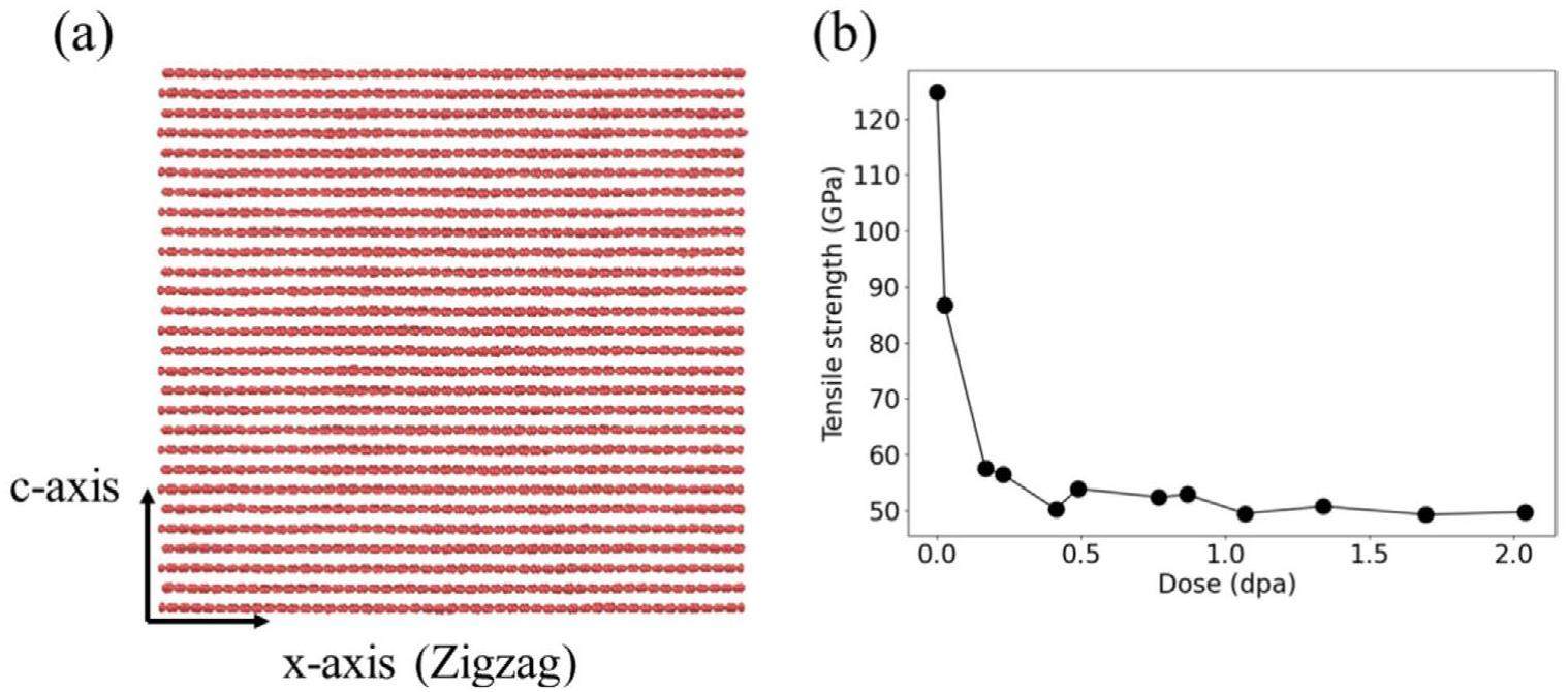
A graphite crystal supercell has been considered here with size of 10 nm × 9.9 nm × 9.5 nm, as in previous works [22, 23, 28], to investigate the microstructural evolution of irradiation defects under applied loading. The supercell consisted of 28 graphite sheets is shown in Fig. 1(a) by using OVITO [37]. These graphite sheets are stacked in the Bernal structure (AB stacking). To balance computational speed and accuracy, the adaptive intermolecular reactive empirical bond order (AIREBO) potential [38] has been employed to describe the interaction between carbon atoms. The AIREBO potential has been used extensively to evaluate the irradiated structures and properties of graphite crystal [22-24, 28, 39]. The ZBL pair potential [40] has been used to describe atomic close-range collisions and the Fermi-type scaling functions [29] has been used to achieve smooth switching between ZBL pair potential and the AIREBO potential. All the aforementioned potentials and MD simulations were performed in the large-scale atomic/molecular massively parallel simulator (LAMMPS) code [41]. These MD simulations were performed at 1073 K (800 ℃) chosen based on the temperature conditions inside a Molten Salt Reactor (MSR).
Irradiated graphite crystal modeling
In this work, irradiation defects are generated by PKA cascades. To create different damage states, a series of impulsing cascades [21] was performed one after the other in the crystal model, until the model was completely amorphous. Multiple PKAs were set with random positions at each impulsing cascade to accelerate the amorphization process. This approach produced a high damage ratio ranging from 0.001 to 0.005 dpa/ps. Considering the limited model size and the PKA energy limit that causes saturation displacement damage [30], the energies of PKAs were set at values below 11 keV with an average value of 8 keV. PKA cascades were performed in the microcanonical (NVE) ensemble. After each irradiation process, the canonical (NVT) ensemble was used to relax the irradiated crystal model, heated by irradiation, to 1073 K and stabilize the potential energy. The NVT relaxation process ensured that irradiation defects were in a stable state, ensuring that the applied loading becomes the primary factor affecting subsequent defect migration process. To analyze displacement damage dose, a neighbor list and initial coordinate reference points were generated for every atom before each irradiation event. Each atomic displacement was determined by checking the displacement distance and IDs in each neighbor list [23, 25] with a cutoff distance of 1.9 Å [25]. If an atom moved more than the cutoff based on thermal diffusion and its original neighbor list changed, the atom was considered it have been knocked out of its equilibrium position.
Microstructural evolution method for crystal creep
Considering that graphite sheets can withstand larger external loads during the loading process, this study investigated the irradiation process and the evolution of damage structures after irradiation when graphite crystal was subjected to tensile loads along the x(a)-axis. However, it is difficult to evaluate an actual engineering creep rate using molecular dynamics method within picoseconds duration. To observe noticeable creep behavior and gain insight into atomic-scale mechanisms, high tensile loads are often applied [34]. These values of different applied tensile loads are referenced to the minimum tensile strength of these irradiated crystal models along the x(a)-axis of these models. Uniaxial tension was conducted at 1073 K using the isothermal-isobaric (NPT) ensemble and periodic boundary conditions to estimate the tensile strength. All tensile strength values and implementation details are shown in Supplementary material S1. By averaging ten independent amorphization processes, the effects of random amorphization can partly be generalized. After the damage dose exceeds 1 dpa, the change in strength becomes less noticeable. The minimum tensile strength remains around 50 GPa, as shown in Fig. 1(b). Therefore, in this study a series of tensile loads was applied to the crystal model within the tensile strength range at values of 1 GPa, 5 GPa, 10 GPa, 20 GPa, 30 GPa, and 40 GPa. Although loads greater than 20 GPa did not reach the minimum tensile strength, they surpassed the elastic region of the stress-strain curve. The higher loads become more similar to shock loads that can induce high-rate plastic strains [27]. The comparison between low and high stress loading can be conducted to reveal the underlying deformation mechanisms of dislocation pinning-unpinning and crystallite yielding [14, 26]. The NPT ensemble has been utilized to apply these applied loads, which can evaluate Poisson's effect and apply stable tensile stress load.
Evaluation methods of irradiation behavior and creep behavior
Threshold displacement energy (Ed) is usually employed to represent the irradiation performance of nuclear graphite [25, 30]. To quantify the effect of the applied tensile loading on the Ed, this study evaluated the average number of defects formed by PKA energies ranging from 10 to 60 eV. One hundred atoms were randomly assigned in the crystal model, ensuring that the distance between any two atoms was greater than 15 Å, which exceeds the maximum PKA displacement observed in previous studies [25, 30]. These atoms are assigned a random velocity distribution, and each energy value is tested ten times with randomly replaced atoms. Consequently, defect formation resulting from each energy value can be evaluated 1000 times. Additionally, to quantify the degree of amorphization caused by irradiation and migration behavior of irradiation defects under applied loading, the proportion of graphitized region (G) and mean square displacement (MSD) were utilized to describe the structure and diffusive properties of defects. G is defined as the ratio of graphitized atomic structures to the total number of atoms in crystal model, which characterizes the extent of irradiation-induced damage to graphitized structures. MSD is defined as the expectation of the square of the displacement value of a group of atoms at a certain moment with respect to the origin moment [34].
Simulation Results and Analyses
Irradiation behavior of graphite crystal under applied tensile loading
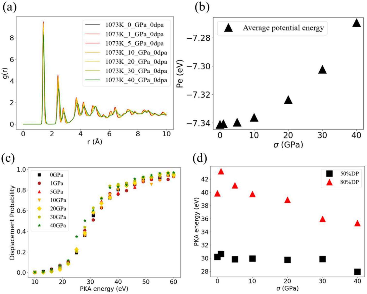
The irradiation behavior of perfect graphite crystal was discussed first. Before each irradiation process, the applied tensile loading was implemented for 300 ps along the x(a)-axis to ensure the stability of the potential energy of the graphite crystal model. Figure 2(a) shows the radial distribution function (RDF) of the graphite crystal model under different applied loads. The RDF is commonly used to describe the atomic density around a central atom and can be employed, similar to characterization methods such as X-ray diffraction, to represent lattice parameters and the degree of order in a crystal structure. The right shift of the RDF peaks in Fig. 2(a) illustrates an increase in atomic distance due to the applied loading. The additional increase based on equilibrium distance can increase the atomic potential energy of the loaded crystal model. Figure 2(b) shows that the average atomic potential energy increases with increasing applied load. Specifically, a load of 40 GPa increases the potential energy by 0.07 eV/atom compared to the state without applied loading. The average atomic potential energy serves as the well depth of potential in which an atom is influenced by its surrounding atoms, to some extent indicating the stability of the structure. Therefore, these changes in crystal structure and atomic potential energy can affect the irradiation performance of graphite crystal, such as threshold displacement energy (Ed) [10]. The Ed reflects the ability of a material to resist irradiation damage, and materials with lower Ed are more likely to experience displacement damage under irradiation. Figure 2(c) shows that as the applied tensile load increases, the displacement probability (probability of lattice atoms leaving equilibrium positions due to irradiation) of lattice atoms in the graphite crystal model decreases at 1 GPa and then continues to increase. The change in PKA energy for 50% displacement-probability and 80% displacement-probability with the applied tensile load (Fig. 2(d)) also shows that the Ed can increase at the initial time and decrease at higher applied tensile loads, which is consistent with the decrease of threshold displacement energy at higher applied strain [10]. Therefore, based on the above results, smaller applied tensile loads of σ< 1 GPa can increase the difficulty of point defect unpinning caused by irradiation in graphite sheets. However, based on like Kelly et al.'s theory, as the applied load continues to increase, unpinning caused by irradiation becomes increasingly likely to occur.
To observe the effect of the changes in crystal structure and threshold displacement energy on PKA irradiation process as well as point defect evolution, a primary damage with insignificant amorphization was first implemented. A PKA with energy of 4 keV was set at the same position for different applied load conditions to observe the irradiation process. Additionally, eight PKAs with energy of 4 keV were placed near the center of the model to study the interactions between PKAs and point defects under applied load. The diagrams of these two PKA processes are shown in Fig. 3(a).

PKA irradiation process and point defect evolution showed significant differences under different applied loads. In Fig. 3(b), the distribution of point defects along the initial incident direction of the PKA is prominent at lower applied loads, but as the applied tensile load increases, the path of the PKA and the distribution of point defects gradually change. One notable phenomenon is the significant limitation of the movement distance of the PKA along the initial incident direction under high applied loads. The PKA in Fig. 3(b) can move further distance along the initial incident direction at lower applied loads, causing the point defect clusters to be preferentially oriented in this direction. However, as the applied tensile load increases, an obstruction along the initial incident direction becomes apparent, leading to a deflection in the path of the PKA and the orientation of the point defect clusters. Ultimately, this results in a more apparent preferred orientation of the point defect clusters along the basal plane, increasing the probability of incident particles causing interlayer pinning and unpinning.
Figure 3(c) indicates that the applied tensile loading can also influence the interaction of PKAs and point defects. The distribution of point defects is more concentrated at lower applied loads under the same PKA irradiation case. Then, the reduced threshold displacement energy and increased atomic potential energy may weaken the interaction between PKA and lattice atoms. As a result, high applied tensile loads might cause an increase in mean PKA displacement relative to the simulation without applied stress [21, 24], resulting in a more dispersed distribution of point defects. As the applied tensile load increases, the mean PKA displacement also increases from 35 Å to 39 Å (From 1 GPa to 10 GPa). At higher applied loads of σ> 10 GPa, hindrance along the initial incident direction restricts the displacement of both PKAs and point defects along the c-axis, leading to a more concentrated distribution of point defect clusters along the a-axis. As a result, higher tensile loads along the a-axis of the crystal model increased the interlayer displacement of incident particles, thereby increasing the probability of unpinning of interlayer dislocations. However, this phenomenon has not been considered in previous theories [5, 14, 26], which may further accelerate irradiation creep rate based on pinning and unpinning theory [14].
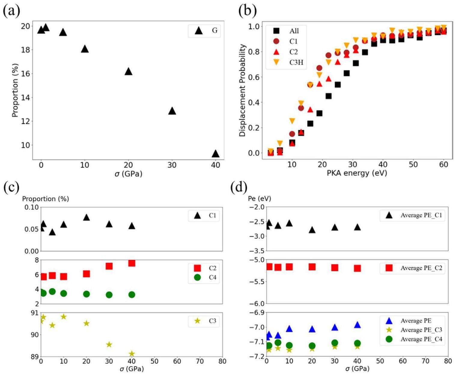
At higher damage doses with significant amorphization, the applied tensile loading also resulted in different damage states compared to the state without applied loading. These random PKA irradiation settings keep the same conditions (same position, velocity direction, and PKA energy) for each applied tensile loading condition. Figure 4(a) illustrates a marked reduction in the proportion of graphitized region (G) under higher tensile loads of σ> 10 GPa, which is consistent with a significant reduction in the threshold displacement energy at loads greater than 10 GPa. In this study, carbon atomic type and potential energy analysis were used as another perspective to investigate the structural changes and mechanisms that occur during irradiation-induced amorphization and loading. During the irradiation process with significant amorphization, the sp2-hybridized atoms located in crystal sheets are converted to other types [23, 42, 43]. The changes of atomic type and potential energy shown in Fig. 4(c, d) indicate that high applied tensile loads can cause more onefold (C1) and twofold (C2) coordinated atoms with higher potential energy, as well as threefold coordinated atoms with higher potential energy (C3H, referring to sp2-hybridized atoms with potential energy higher than those of undistorted carbon lattice planes). Meanwhile, the proportion and average potential energy of threefold (C3) and fourfold (C4) coordinated atoms also increase with increasing tensile load, thus increasing the average atomic potential energy of the irradiated crystal model. Moreover, these atoms with higher potential energy exhibit lower threshold displacement energy as demonstrated in previous studies [25, 42] and shown in Fig. 4(b). Consequently, they are more susceptible to displacement by irradiation, potentially leading to enhanced diffusion [44] and an accelerated irradiation creep under applied loading.
Creep behavior of irradiated crystal under applied tensile loading
To investigate the creep behavior of irradiated crystal, different applied tensile loads were applied along the x(a)-axis. The strain curves over time under various applied loads and damage doses are shown in Supplementary material S2. The steady state creep rate (SSCR) [45] along to the x(a)-axis in Fig. 5(a, b) is fitted using the strain curves from the last 100 ps. However, the tensile loading of 40 GPa is approaching the minimum tensile strength, which results in an excessively rapid strain rate in the crystal model. Therafore, at 40 GPa only some converged results are shown here. The resulting creep curves illustrate that even if the applied load exceeds 30% of the tensile strength of perfect crystal, the perfect crystal does not show significant creep behavior at 1073 K. However, when the complete crystal structure is damaged by irradiation, Fig. 5(b) show that the crystal model exhibits creep behavior under high applied load of σ > 10 GPa at 0.03 dpa. Furthermore, the primary creep and SSCR increase with the increase of damage dose and applied load.
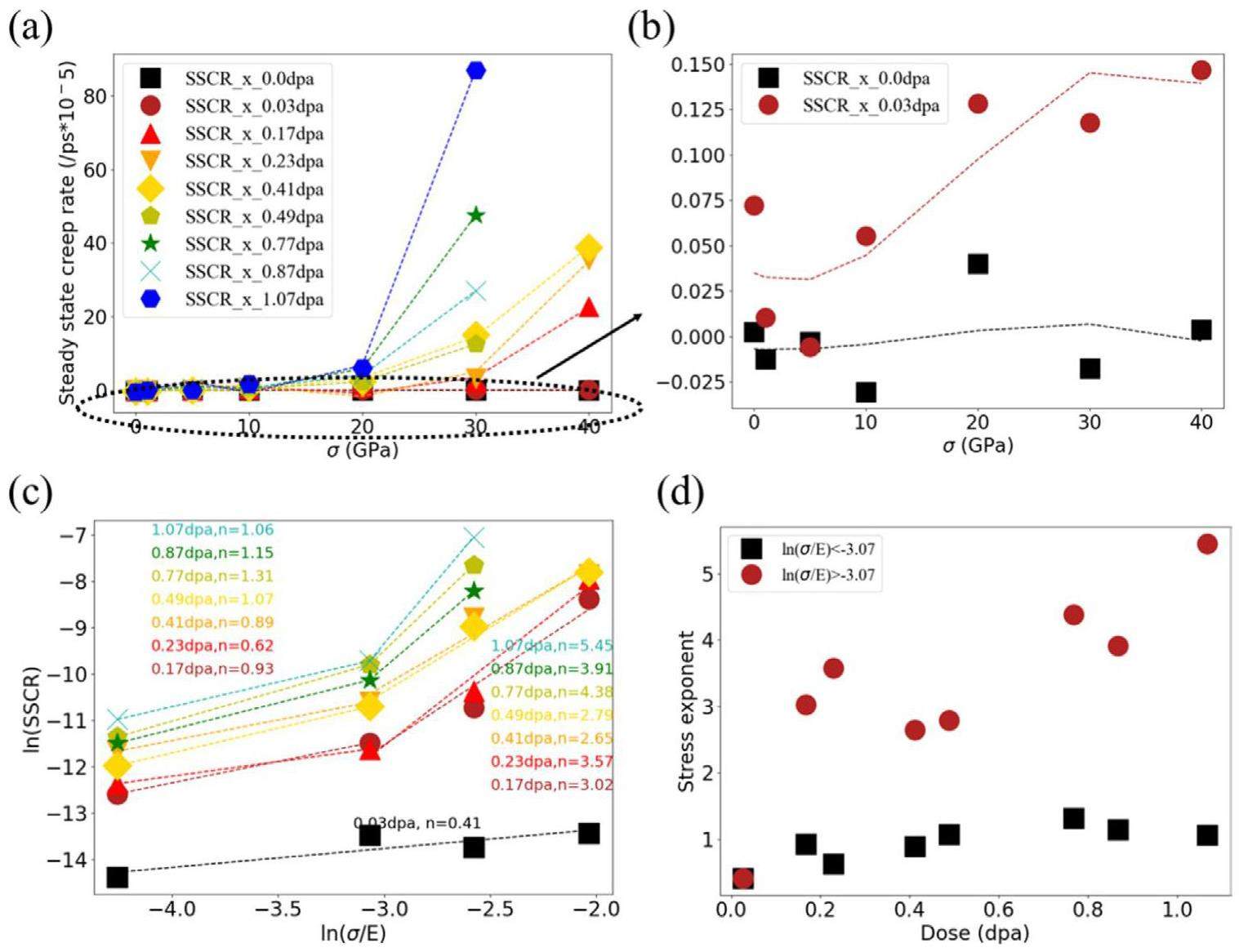
Meanwhile, the effect of damage dose and applied loading is observed to differ in various states, as shown in Fig. 5(a, b). At the applied loads of σ< 10 GPa and damage doses (< 0.17 dpa and G > 30%), the tensile loading only changes the dimensional changes produced by irradiation and does not cause significant creep behavior. Then a slight creep phenomenon occurs as the applied load increases. However, at higher damage dose, creep behavior becomes more pronounced with increasing applied load. The steady state creep rate in Fig. 5(a) shows that the applied tensile loading significantly influences the creep behavior at higher damage dose, which can be related to the decreasing tensile strength due to irradiation. The study by Sarkar et al. also indicates that irradiation creep behavior is sensitive to irradiation dose [12]. Their rate theory shows that [12]
Analysis of creep mechanism
The significant difference in the stress exponent observed in Fig. 5(c, d) under different damage states and loads indicates that the creep mechanism may differ. To understand the creep mechanism of irradiated graphite crystal, MSD analysis and visual atomic structure analysis were used to reveal the diffusion properties of defects and structure changes in each damage state. Figure 6(a) and Fig. 7(a) indicate that perfect crystal sheets are more prone to slip, and the applied tensile loading increases the trend of interformational sliding. Figure 6(a) shows that under the influence of applied tensile loading, there is a significant displacement of crystal atoms along the a-axis, while there is no noticeable migration along to the z(c)-axis. By combining the MSD analysis in Fig. 6(a) and visual structural analysis in Fig. 7(a), it can be deduced that the significant migration phenomenon along the a-axis is a consequence of the overall slip of graphite sheets. But the sliding did not cause significant creep strain. At the damage dose of 0.03 dpa (G > 70%), interstitials and vacancies are the primary types of irradiation defects and strongly restrict the interformational sliding, as illustrated in Fig. 7(a). As a result, significant diffusion cannot be observed at lower applied loads, as shown in Fig. 6(b). However, with the increase of the applied load, a slight diffusion effect occurs along the x(a)-axis. Furthermore, compression in the z(c)-axis can be observed, and whereas the atomic displacement in the y(a)-axis increases with the applied load.
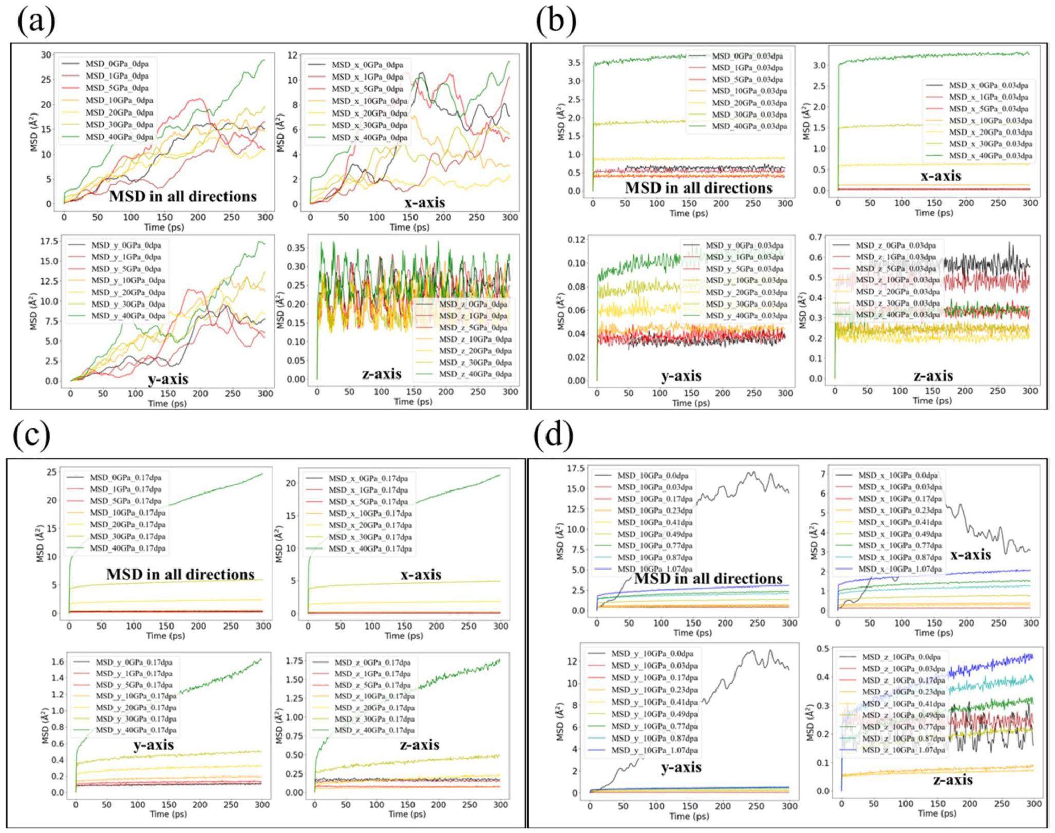
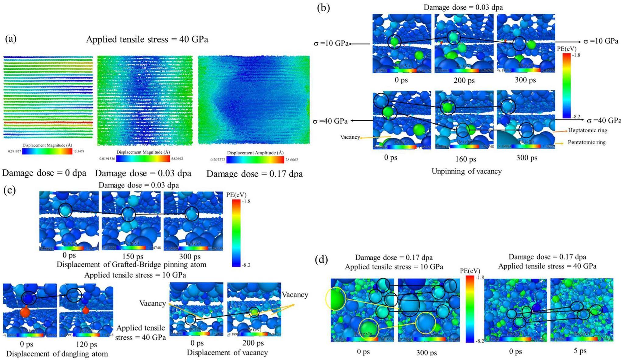
Figure 5(b) shows that lower applied tensile loads of σ< 10 GPa did not lead to the significant creep behavior at 0.03 dpa. However, the MSD analysis in Fig. 6(b) reveals the occurrence of defect migration even under lower tensile loads, particularly evident in the y-axis direction. This indicates that these defects, such as interstitial atoms, undergo migration. The type of damage state aligns with the dislocation pinning-unpinning model proposed by Kelly et al., thus providing verification of the structural mechanism of their model. Visual structural analysis also confirms the specific patterns of dislocation pinning-unpinning (Pinning refers to the connection of interstitial atoms entering the interlayer with vacancy dislocation defects in the upper and lower graphite sheets, thereby fixing and anchoring the dislocations, hence referred to as pinning atoms by Kelly et al. [14]. At an applied load of 10 GPa, the main mode of migration for these pinning atoms in the basal plane occurs through a defect type conversion of interstitials, which requires less activation energy. Figure 7(b) shows that an interstitial atom of Wallace combines with a sp-hybridized atom on the edge of the vacancy to form a new defect under the action of 10 GPa applied tensile loading. Additionally, Fig. 7(c) shows the migration of a Grafted-Bridge atom by bonding and breaking bonds with surrounding sp2-hybrid atoms. In this migration mode, the conversion of intermediates is involved, which limits the migration distance and results in insignificant diffusion and creep. However, considering the irradiation behavior described in Sect. 3.1, the effects of irradiation under applied loading may accelerate the unpinning of such interlayer pinning structures, thereby contributing to an increasing defect migration rate and creep strain.
High applied loads can directly break the bond between interstitial atoms and the basal plane. Figure 7(b) shows the unpinning process of the same interstitial atom of Wallace at 40 GPa, as compared to the process at 10 GPa. The bond between the interstitial atom of Wallace and upper basal plane is broken by the high applied loading, leading to the backward movement of the pinning and the forward movement of vacancy. In this way, these defects can move larger distances, thus causing a more pronounced diffusion phenomenon, as shown in Fig. 6(b). Figure 7(c) also shows that the dangling atoms can jump and migrate directly, and vacancies can migrate by breaking the bonds of the edges under an applied load of 40 GPa. Since these defects migrate in the basal plane, which may cause diffusion phenomenon in the y-axis as well. By directly breaking and migrating bonds in this manner, the migration rate of defect structures and the creep rate increase rapidly, which explains the significant differences in the stress exponent at high stress levels (ln(σ/E) > 3.07) observed in Fig. 5(d). Simultaneously, the rapid bond-breaking migration facilitated by pinning structures leads to the rapid migration of the entire basal plane and irradiation structure under external loading, resulting in plastic deformation and ultimately crystal yield. In contrast, for intact graphite sheets, the strong interlayer sliding allows the graphite sheets to bear the main load, making them prone to brittle fracture. This may explain the occurrence of “nanoscale kink band mediated plasticity” observed by Thomas et al. during the micro-pillar compression of irradiated graphite [27].
In the damage state where amorphous regions are clearly present, the layered structure for the dislocation pinning-unpinnin mode gradually disappear, giving way to the amorphous structure which becomes the main type of irradiation defects. A higher stress exponent indicates that an atomic diffusion mechanism can be dominant [12, 14], which is supported by MSD analysis in Fig. 6(c, d) and visual structural analysis in Fig. 7(d). Both the creep and diffusion rate increase significantly with the applied tensile load and damage dose. Furthermore, the diffusion phenomenon along the c-axis can also be observed, as shown in Fig. 6(c, d). Figure 7(d) show the specific atomic diffusion modes within the amorphous region. The visual structural analysis in Fig. 7(d) indicate that triangular defects, quadrilateral defects and other types of defects with higher potential energy are more susceptible to conversion by the applied tensile loading. Figure 7(d) show that the threefold coordinated atom of the triangular defect undergoes conversion to a twofold coordinated atom at 40 GPa. These atoms can quickly migrate over short distances by breaking their existing bonds and forming new ones with the surrounding atoms. Furthermore, due to the absence of hindrance from graphite layered structure, atoms can also migrate rapidly along the z(c)-axis, resulting in diffusion phenomena along the z(c)-axis.
Analysis of creep behavior
The analysis of stress exponent in Fig. 5(c, d) reveals applied tensile loads and damage dose can cause differences in creep behavior. Moreover, the structure analysis in previous section indicates that the defect migration mechanism at different damage structures and applied tensile loads may be the main reason for the great difference in stress exponent. Therefore, with reference to [12], the empirical relationship between the applied tensile load and SSCR along to the x(a)-axis can be describe as:
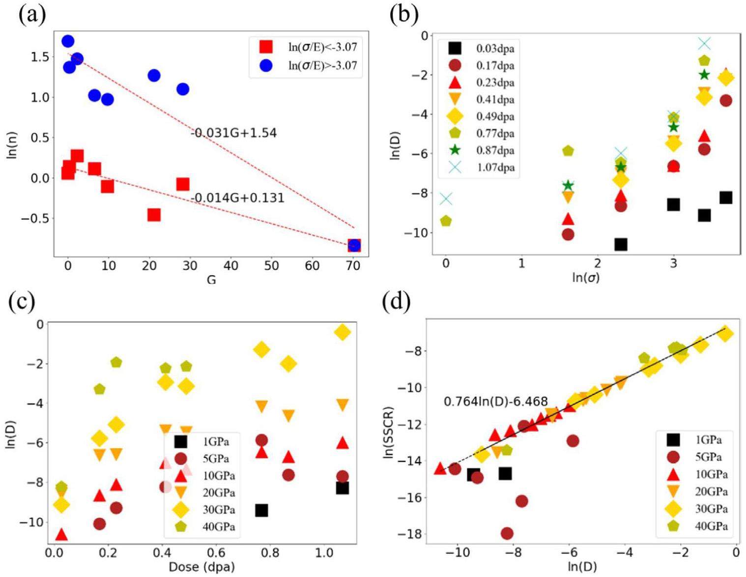
In addition, applied tensile loading and damage structures also influence the relationship between diffusion behavior and creep behavior. Figure 8(b, c) show that
Discussion
Irradiation creep effect runs through the entire service life of nuclear graphite, and the difference in dimensional changes at bulk scale is typically used to measure the creep phenomenon [2, 5]. However, to fully understand the underlying mechanism, a microscopic analysis is necessary. The changes in dimension and material properties of graphite bulk depend on the structural change of crystallites at micro-and nanoscale [5, 14, 20, 46]. Therefore, the structural analysis of graphite crystals under irradiation and applied loads is critical to reveal some mechanisms of irradiation creep. In this paper the molecular dynamics method was employed to investigate the effect of applied tensile loading on the irradiation behavior of graphite crystals, as well as the migration behavior of irradiation induced defects.
The results suggest that, in a perfect crystal state, applied tensile loading exerts a significant impact on both the crystal structure and threshold displacement energy. Specifically, the observed right shift of RDF peaks at higher loads signifies an increase in the atomic distance. This, in turn, results in a reduction in the average atomic potential energy and threshold displacement energy. Previous research, such as the work from Hu et al. [10], has shown that high tensile loads can decrease the threshold displacement energy and accelerate irradiation damage. Our work further shows that high applied tensile loads can weaken the interaction between PKAs and lattice atoms, as well as between PKAs themselves, resulting in more carbon atoms with higher potential energy. Moreover, the threshold displacement energy of these atoms is lower, thus accelerating atomic diffusion under irradiation and applied loads. Figure 5 and Fig. 6 also indicate the creep rate and diffusion rate increase with the increase of these atoms with higher potential energy.
As changes occur in both the crystal structure and threshold displacement energy, the irradiation behavior also shows differences under different applied tensile loads. In the absence of any applied load, the PKA follows its initial incidence direction, resulting in a distribution of point defect clusters that are also preferentially oriented along this incidence direction. However, high applied tensile loads can restrict the displacement of PKA along the initial incident direction, thus causing the preferred orientation of the point defect cluster distribution along the a-axis. One possible explanation for this phenomenon is that the applied tensile load imposes additional internal stress on each crystal sheet, increasing their resistance to the PKA. In other words, the high applied tensile loads constrains the movement of the PKA cross the layers, resulting in a preferred orientation of point defects along the a-axis. This phenomenon increases the interlayer displacement of incident particles, coupled with the decrease in threshold displacement energy due to external loading, making the interlayer pinned dislocation structures more susceptible to unpinning under irradiation. However, previous creep studies did not account for the effects of external loading-induced changes in irradiation behavior.
From the analysis of the creep and diffusion behavior reveals that the underlying creep mechanisms vary depending on the extent of damage and the applied tensile load. The stress exponent indicates that in the absence of obvious amorphous regions, the pinning and unpinning mode may be the main model of creep for irradiated crystals. Moreover, there is a conversion of intermediate for unpinning under lower applied loads, which constrains the migration of pinning atoms and causes insignificant creep and diffusion. However, high applied loads can directly break the connection of pinning atoms, leading to slight creep phenomena, which explains the split in stress exponent observed in Fig. 5(d) due to different stress levels. In a state with significant amorphous regions, atoms with lower potential energy tend to migrate more easily. With the increase of amorphous regions, more atoms migrate by breaking bonds and re-bonding with surrounding atoms, thus accelerating creep. Moreover, due to the disappearance of the crystal layer structure, these atoms can migrate in other directions, allowing for diffusion phenomena other than the a-axis, as shown in Fig. 6. This type of creep mechanism may dominate in the grain boundaries and non-graphitized regions of nuclear graphite.
Conclusions
The study aims to investigate the effects of applied tensile loading on the irradiation and creep behavior of graphite crystals, with the goal of shedding light on some mechanisms underlying changes of nuclear graphite properties and irradiation creep in nuclear reactors. The following conclusions can be drawn from our findings:
1. High applied tensile loads along x(a)-axis increase atomic potential energy and reduce threshold displacement energy of graphite crystals, thereby weakening the interaction between PKAs and irradiation defects, resulting in differences in defect distribution after irradiation, and accelerating the amorphization process and irradiation-enhanced diffusion.
2. The underlying irradiation creep mechanisms vary depending on the extent of damage and the applied tensile load. In the absence of obvious amorphous regions, the phenomenon of pinning-unpinning can be observed. Moreover, a conversion of intermediates is observed in the unpinning process under lower levels of applied load. However, with the disappearance of graphitized structure, atomic diffusion mechanism becomes the primary mechanism responsible for irradiation-induced creep in graphite crystals.
Analysis of the dimensional changes and structural-changes in polycrystalline graphite under fast-neutron irradiation
. Carbon 31, 155-178 (1993). https://doi.org/10.1016/0008-6223(93)90169-BThe analysis of irradiation creep experiments on nuclear-reactor graphite
. Carbon 32, 119-125 (1994). https://doi.org/10.1016/0008-6223(94)90017-5The effect of high fluence neutron irradiation on the properties of a fine-grained isotropic nuclear graphite
. J. Nucl. Mater. 230, 1-7 (1996). https://doi.org/10.1016/0022-3115(96)00005-0The effect of neutron irradiation damage on the properties of grade NBG-10 graphite
. J. Nucl. Mater. 371, 18-27 (2007). https://doi.org/10.1016/j.jnucmat.2007.05.021Dimensional change, irradiation creep and thermal/mechanical property changes in nuclear graphite
. Int. Mater. Rev. 61, 155-182 (2016). https://doi.org/10.1080/09506608.2015.1136460Analyses of a restrained growth graphite irradiation creep experiment
. Nucl. Eng. Des. 238, 3026-3030 (2008). https://doi.org/10.1016/j.nucengdes.2007.12.017Observations of crystal strains in filler and QI particles through TEM examination - Effect of processing and grain size
. Mater. Design. 204,A macro-scale ruck and tuck mechanism for deformation in ion-irradiated polycrystalline graphite
. Carbon 173, 215-231 (2021). https://doi.org/10.1016/j.carbon.2020.10.086A multiscale modelling of polycrystalline nuclear graphite under effect of microcracks and incomplete-graphitized regions
. J. Mater. Res. 38, 675-685 (2023) https://doi.org/10.1557/s43578-022-00849-yEffect of stress on irradiation responses of highly oriented pyrolytic graphite
. Materials. 15, 3415 (2022). https://doi.org/10.3390/ma15103415Ukaea reactor group studies of irradiation-induced creep in graphite
. J. Nucl. Mater. 65, 79-85 (1977). https://doi.org/10.1016/0022-3115(77)90044-7Modeling irradiation creep of graphite using rate theory
. J. Nucl. Mater. 473, 197-205 (2016). https://doi.org/10.1016/j.jnucmat.2016.01.036The various creep models for irradiation behavior of nuclear graphite
. Nucl. Eng. Des. 242, 19-25 (2012). https://doi.org/10.1016/j.nucengdes.2011.09.024The theory of irradiation creep in reactor graphite-The dislocation pinning-unpinning model
. Carbon. 12, 151-158 (1974). https://doi.org/10.1016/0008-6223(74)90021-9Studies of irradiation creep on core graphite by thermal annealing
. J. Nucl. Mater. 539,Interlayer binding energy of graphite: A mesoscopic determination from deformation
. Phys. Rev. B. 85, (2012). https://doi.org/10.1103/PhysRevB.85.205418Optimized geometries and electronic structures of graphyne and its family
. Phys. Rev. B. 58, 11009-11014 (1998). https://doi.org/10.1103/PhysRevB.58.11009Wigner defects bridge the graphite gap
. Nat. Mater. 2, 333-337 (2003). https://doi.org/10.1038/nmat876X-Ray Diffraction Studies of Neutron-Irradiated Graphite
. Acta Crystallogr. 9, 1029-1035 (1956). https://doi.org/10.1107/S0365110x56002989Early stages of radiation damage in graphite and carbon nanostructures: A first-principles molecular dynamics study
. Phys. Rev. B. 75,Atomic scale mechanisms for the amorphisation of irradiated graphite
. Carbon 91, 395-407 (2015). https://doi.org/10.1016/j.carbon.2015.05.003Molecular dynamics simulations of irradiation defects in graphite: Single crystal mechanical and thermal properties
. Comp. Mater. Sci. 113, 60-65 (2016). https://doi.org/10.1016/j.commatsci.2015.11.012A time-dependent atomistic reconstruction of severe irradiation damage and associated property changes in nuclear graphite
. Carbon 120, 111-120 (2017). https://doi.org/10.1016/j.carbon.2017.05.009Morphology evolution and defect distribution in irradiated graphite from molecular dynamics
. Comp. Mater. Sci. 155, 246-255 (2018). https://doi.org/10.1016/j.commatsci.2018.08.056Evolution of threshold displacement energy in irradiated graphite
. Phys. Rev. Appl. 10,Creep of alpha uranium during irradiation with neutrons
. Philos. Mag. 1, 711-717 (1956).Real-time observation of nanoscale kink band mediated plasticity in ion-irradiated graphite: An in situ TEM study
. Materials 17, 895 (2024). https://doi.org/10.1103/10.3390/ma17040895Thermal resistance from irradiation defects in graphite
. Comp. Mater. Sci. 103, 68-76 (2015). https://doi.org/10.1016/j.commatsci.2015.03.001Simulating radiation damage cascades in graphite
. Carbon 81, 105-114 (2015). https://doi.org/10.1016/j.carbon.2014.09.031Threshold displacement energy and damage function in graphite from molecular dynamics
. Carbon 99, 71-78 (2016). https://doi.org/10.1016/j.carbon.2015.11.040Irradiation induced grain boundary flow-A new creep mechanism at the nanoscale
. Nano. Lett. 12, 4084-4089 (2012). https://doi.org/10.1021/nl301554kCoupling effects of stress and ion irradiation on the mechanical behaviors of copper nanowires
. Sci. China-Phys. Mech. 56, 498-505 (2013). https://doi.org/10.1007/s11433-013-5008-6The effect of temperature on creep behaviour of porous (1 at.%) nano crystalline nickel
. Trans. Indian Inst. Met. 69, 277-282 (2016). https://doi.org/10.1007/s12666-015-0763-xNature of creep deformation in nanocrystalline Tungsten
. Comp. Mater. Sci. 149, 360-372 (2018). https://doi.org/10.1016/j.commatsci.2018.03.040A novel displacement cascade driven irradiation creep mechanism in alpha-zirconium: A molecular dynamics study
. J. Nucl. Mater. 541,A molecular dynamics study of a cascade induced irradiation creep mechanism in pure copper
. J. Nucl. Mater. 560,Visualization and analysis of atomistic simulation data with OVITO-the Open Visualization Tool
. Model. Simul. Mater. Sc. 18,A reactive potential for hydrocarbons with intermolecular interactions
. J. Chem. Phys. 112, 6472-6486 (2000). https://doi.org/10.1063/1.481208High-temperature annealing of graphite: A molecular dynamics study
. J. Nucl. Mater. 503, 157-163 (2018). https://doi.org/10.1016/j.jnucmat.2018.03.011Fast parallel algorithms for short-range molecular-dynamics
. J. Comput. Phys. 117, 1-19 (1995). https://doi.org/10.1006/jcph.1995.1039Defect structure classification of neutron-irradiated graphite using supervised machine learning
. Nucl. Eng. Technol. 54, 2783-2791 (2022). https://doi.org/10.1016/j.net.2022.02.021Defect formation and bending properties in graphite under He atom implantation investigated by molecular dynamics method
. Carbon 191, 350-361 (2022). https://doi.org/10.1016/j.carbon.2022.01.059Irradiation-enhanced diffusion and diffusion-limited creep in U3Si2
. J. Nucl. Mater. 555,Experimental correlations for high-temperature creep
. Asm. Trans. Q. 62, 155 (1969).Modelling the coefficient of thermal expansion in graphite crystals: implications of lattice strain due to irradiation and pressure
. Proc. R. Soc. A 474,The authors declare that they have no competing interests.

