I. INTRODUCTION
Radiation shielding calculation of large scale nuclear facilities is complicated due to the bulk shield and complex geometry. Discrete ordinates (SN) and Monte Carlo (MC) methods are commonly used in the design of radiation shielding. MC method is able to treat the complex geometry, but time-consuming in dealing with the deep penetration problems. SN method has great computational efficiency, but it is quite costly in computer memory. Therefore, for the shielding analysis of a large and complex system, the coupled method which combines the advantages of both the MC and SN approaches is very suitable. The MC method is used to simulate the particle transport in the complex geometry, and the SN method is used to treat the deep penetration problems in the bulk shield.
The existing SN-MC coupled codes include DOT-DOMINO-MORSE [1] and DORT-PROBGEN-MCNP [2]. However, these codes cannot support full three-dimensional geometry. Masahiko Kurosawa developed TORT-MCNP [3] for the calculation of neutron flux around a core of BWR, but it only for Cartesian geometry. In this work, a program system has been devised to make full three-dimensional SN-MC coupling calculations in both Cartesian and Cylindrical geometry. The validation calculation of the H. B. Robinson Unit 2 (HBR-2) pressure vessel benchmark problem [4] is presented and discussed.
II. SN-MC COUPLED METHOD
To perform the SN-MC calculation, the model is divided into two parts. The one part of the model is the bulk shield region with simple geometry, and the other part is the complex geometry. The discrete ordinates method has advantage in treating the deep penetration problem with simple geometry. The MC method is able to treat the complex geometry, but time-consuming in dealing with the deep penetration problem. In order to eliminate the weakness of the single method, an interface program is developed to transform the angular fluxes from SN solution into normalized probability distributions. The normalized probability distributions calculated by interface program are as follows:
where ψ(ri, Eg, Ωm) represents the angular flux in the spatial mesh i for energy group g and direction m. I is the total number of spatial mesh, G is the total number of energy groups, M is the total number of directions. λm means direction cosine with respect to a set of orthogonal coordinate axes. wM is the corresponding directional weight. Ai means the area of the spatial mesh i. The probability of any spatial mesh, p(i), is calculated by Eq. 1 based on the radio of the total number of particles crossing at that location to the total number of particles crossing the entire common surface. p(g/i) in Eq. 2 is the normalized energy spectrum. Eq. 3 defines the probability for every angle used in the discrete ordinates method. That is, if the calculation used an S8 quadrature scheme, then there would be 80 probabilities, each corresponding to a unique direction.
The space bin is chosen by Eq. 4, and ξ means a random number. The energy and angular bin selection were conducted in the same fashion as shown in Eq. 4, and the final energy and direction were sampled randomly from within the selected bin.
III. PROGRAM SYSTEM
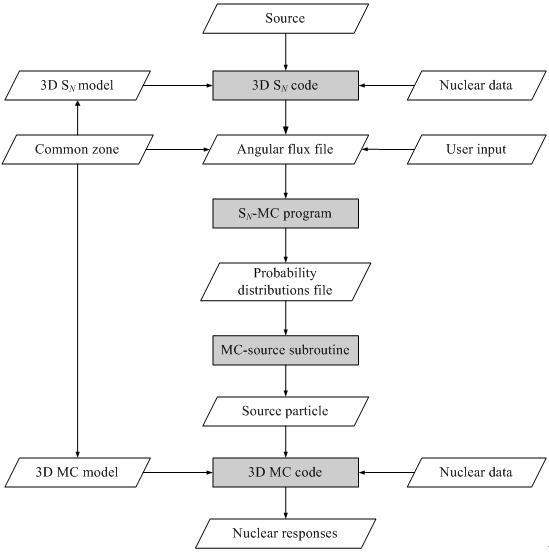
The flow chart of three-dimensional SN-MC coupled program system was shown in Fig. 1. The coupled program system consists of three-dimensional SN code, SN-MC interface program, MC source subroutine and MC code.

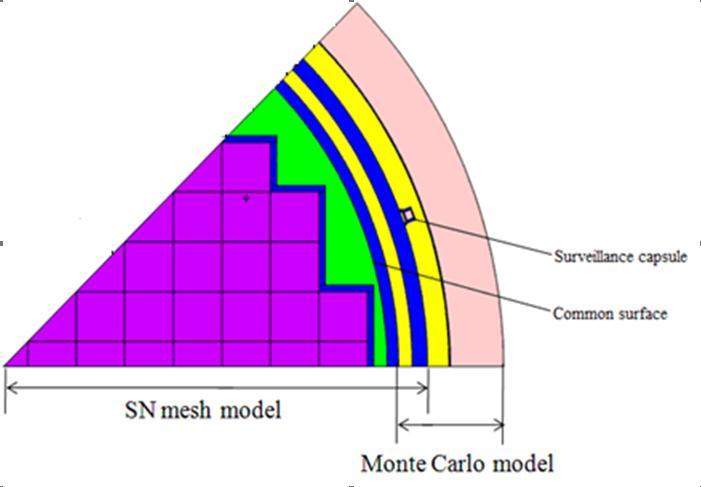
In practical application, a common surface is first specified in both SN mesh model and the MC model. In SN calculation, the angular fluxes (as a function of mesh interval, energy group and discrete direction) on the common surface are stored in a BNDRYS formatted file. In MC simulation, this surface is specified as the source. The interface program reads the BNDRYS-format file generated by SN, and then uses the equation given in Section 2 to generate the necessary probability distributions. The MC source subroutine is linked to MC code to generate MC source particles variables by using the probability. The Cartesian (X, Y, Z) and Cylindrical (R, θ, Z) can be selected in the calculation by the coupling method.
IV. CALCULATION RESULTS AND DISCUSSION
The HBR-2 benchmark was adopted to validate the capability of the 3D SN-MC coupling methodology. The specific activities for the six dosimeters were calculated. The dosimeters were irradiated during cycle 9 in the surveillance capsule. The surveillance capsule is located on the mid-place of the HBR-2 core. The experimental measurements and results of DORT code are included in the benchmark documentation. The 45

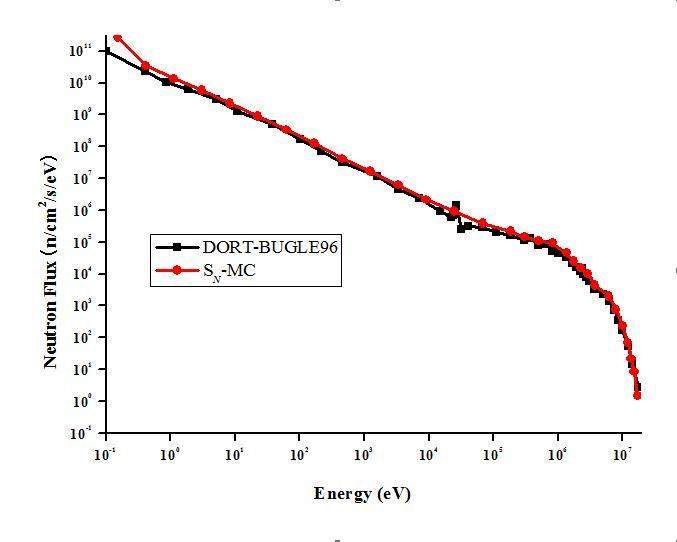
For SN calculation, the order of scattering expansion is P3, and the angular quadrature set is S8. The mesh grids for the SN model are 110×36×48. The angular fluxes on the common surface, calculated by TORT, were stored in a BNDRY format file, and then the interface program and the source subroutine were employed to generate the source particles of MCNP. The MC model describes the detailed geometry and material compositions of surveillance capsule mounting on the thermal shield. The neutron flux values and activities at the dosimeter position of the surveillance capsule are calculated by SN-MC coupled method. It is seen from Fig. 3 that the SN-MC neutron spectrum appears to be in relatively good agreement with the DORT-BUGLE96 solution in HBR-2 benchmark report.

The ratios of the calculated specific activities by different codes with the measurements were shown in Table 1. The average ratios of calculated-to-measured (C/M) for the six dosimeters in the surveillance capsule for DORT, SN-MC and TORT are 0.90±0.04, 1.03±0.04 and 1.04±0.04, respectively. The C/M of DORT and TORT come from [4] and [8], respectively. Table 1 shows that the SN-MC calculated specific activities are quite similar to the TORT results and the experimental measurements. As to be expected from the neutron flux comparisons, the SN-MC calculated specific activities are larger than the DORT results. The necessary simplification of certain features for the HBR-2 reactor, the different codes and cross-section library differences can all be the contributing factors.
| Code | 237Np(n,f) 137Cs | 238U(n,f) 137Cs | 58Ni(n,p) 58Co | 54Fe(n,p) 54Mn | 46Ti(n,p) 46Sc | 63Cu(n,a) 60Co | Average |
|---|---|---|---|---|---|---|---|
| DORT | 0.90 | 0.85 | 0.96 | 0.93 | 0.85 | 0.90 | 0.89±0.04 |
| SN-MC | 1.06 | 0.96 | 1.01 | 1.03 | 1.01 | 1.09 | 1.03±0.04 |
| TORT | 1.12 | 1.07 | 1.00 | 0.99 | 1.03 | 1.05 | 1.04±0.04 |
V. CONCLUSIONS
A program system has been developed to implement the coupled SN-MC scheme by integrating the 3D SN code TORT, the MC transport code MCNP, the coupling interface program and source subroutine. The program system is able to deal with the shielding problem with bulk shield and complex geometry in large dimensions. The HBR-2 benchmark problem has been performed to validate the program system. Good agreements were obtained by comparing with the measurements and the results of other codes. The successful application demonstrates that the coupling scheme with the program system is a powerful computational tool for three-dimensional shielding analysis of complex and large nuclear facilities.
IAEA-NDS-176: FENDL/MG-2.0 and FENDL/MC-2.0
,
