I. INTRODUCTION
A linear proton accelerator (Linac), called Inject I, with continuous wave model (CW operation) and designed beam parameter 10 MeV–10 mA, will be constructed in Institute of High Energy Physics, Chinese Academy of Sciences. The Linac, as advanced research equipment, can be one choice of the two injectors for further high energy accelerator, which is an important constituent part for the China-Accelerator Driven Sub-critical System (C-ADS).
For this equipment was planned to establish in an existing tunnel, detailed radiation shielding simulations are performed and the existing shielding structure is checked and re-designed. The radiation shielding hot spots are optimized including thickness of the shielding concrete wall, construction of the beam dump and local additional concrete shielding, re-designed cable hole, shielding door made by composite material. This work will focus on different shielding schemes according to the radiation levels and the space limits. All the design skills and various shielding structures are presented in this paper, which may provide use for reference to the similar project.
II. DESIGN METHODS
The structure of the existing tunnel hall is shown in Fig. 1. The main dimension of the tunnel structure and the layout of the accelerator devices in the tunnel are shown at the same time. The tunnel contains more than ten cable holes inside the bottom of the south/north shielding walls (ploted by dashed lines). In the east wall of the tunnel, a new shielding door is designed for the equipment transportation, whose shielding effect should almost equal to the nearby concrete wall. The beam loss is less than 1 W/m in the linear part and the beam energy is from 35 keV at ECR section to 10 MeV at the end of CM section, 10 MeV–1 W/m beam loss parameter is adopted in the simulation conservatively (called linear loss situation). It is important to note that the beam dump, which was designed for absorbing 10 MeV–10 mA proton beam, is also located in the tunnel, so, 10 MeV–10 mA beam loss parameter is adopted in the simulation. In low energy region, the hydrogenous material is effective for the neutron shielding; common concrete was chosen to be the shielding material in most places, for it is economical and also effective for gamma shielding.

All the simulations were finished using FLUKA code [1]. Variance reduction technique and the linear sampling method [2] were used in the simulations. In order to reduce the statistical errors, the number of primary particle is set more than 107 and the running cycle is more than forty times. Structure of the tunnel and the added shielding blocks were constructed as true as possible in the geometry building.
According to the national standard GB 18871-2002, the occupational exposure limit is 20 mSv per year. However, considering the ALARA (as low as reasonably achievable) philosophy, the radiation dose management goal for this project is 5 mSv per year. For the sake of convenience, the designed goal is that the dose rate outside the tunnel should be below 2.5 μSv/h.
III. RESULTS AND DISCUSSION
A. Thickness of shielding concrete wall
As mentioned above, this Linac will be constructed in the existing tunnel hall, and two different beam loss parameters are adopted during the radiation shielding design, so the first thing is to make sure whether the existing concrete shielding structure is thick enough to prevent the radiation penetrating through the wall. As is well known, the neutron radiation is the main consideration for the proton accelerator radiation shielding; this is obvious as shown in Figs. 3 and 7. The curves in Figs. 2, 5, 10, only represent the total radiation dose rate, which is sum of neutron dose rate and gamma dose rate.
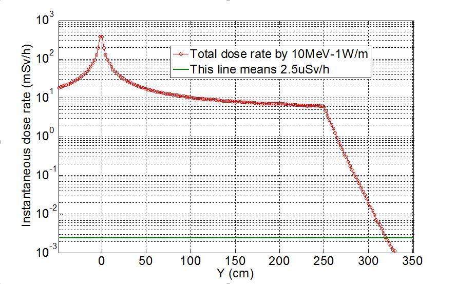
Figure 2 shows the total prompt dose rate attenuation curve during the linear loss situation. Y axis is perpendicular to the beam pipe, Y=0 cm is the beam pipe; Y=250 cm is inner wall of the tunnel; Y greater than 250 cm is the concrete wall. As we can see, the maximum dose rate position is in the center of the beam pipe; the value is about 400 mSv per hour and decreases quickly away from beam pipe. It is obvious that 80 cm thickness concrete wall is needed to ensure radiation dose rate meet the designed goal.
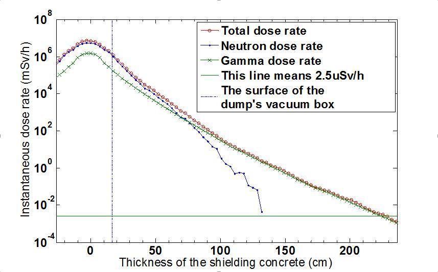
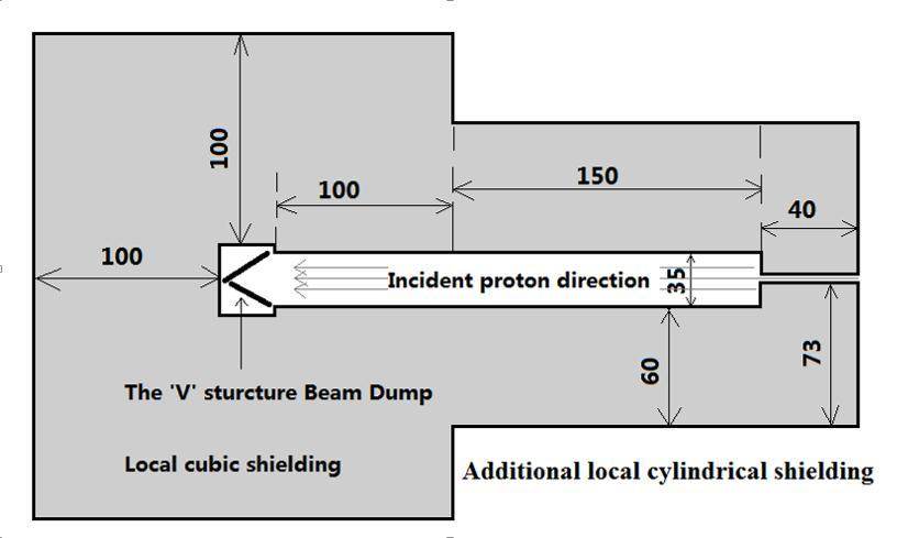
As shown in Fig. 1, the beam dump is located inside the tunnel and the thickness of the adjacent concrete wall is 120 cm. We can see from Fig. 3, when 10 MeV–10 mA proton beams are collected by the beam dump the maximum dose rate is about 107 mSv/h in the center of the dump. In order to reduce the dose to the designed value, nearly 220 cm thickness concrete is needed. So, besides the shielding effect of the adjacent 120 cm thickness concrete wall, 100 cm thickness local cubic concrete shielding is needed as shown in Fig. 4.
B. Beam dump and additional local cylindrical shielding
For the reason that the beam dump used in this project must absorb 10MeV–10mA proton beam in CW operation, so heat dissipation and radiation shielding are the two important problems[3, 4]. For better heat dissipation, the beam cross section is expanded by a special magnet located in front of the dump, and a 'V’ structure beam dump was designed as shown in Fig. 4, which was made by Cu material with a thin layer of Ni plating on its inner surface, which is cooled by circulating water. The head distribution in the two plates was calculated by the physical design staff using ANSYS program. The radiation shielding design is the main issue discussed in this paper.
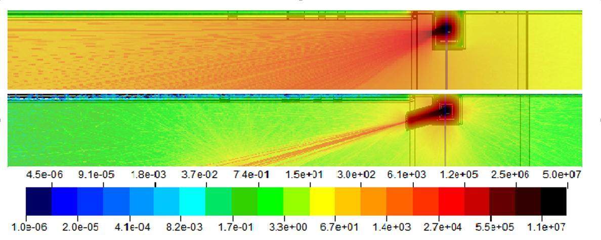
According to above analysis, 100 cm thickness local cubic concrete shielding is needed for the beam dump, but the expanding beam cross section will result in a severe back-streaming radiation to the devices in front of the dump, so, an additional local cylindrical shielding scheme was proposed as shown in Fig. 4. Two cylindrical concrete shielding parts with different radius were added in front of the dump. Through multiple simulations, the final optimized sizes of each part were marked in Fig. 4. The comparison of the total radiation levels in the tunnel during different shielding structures is shown in Fig. 5. We can predict that the additional local cylindrical shielding sharply could reduce the radiation level in the tunnel.
C. Re-design of cable pipe hole
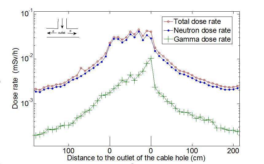
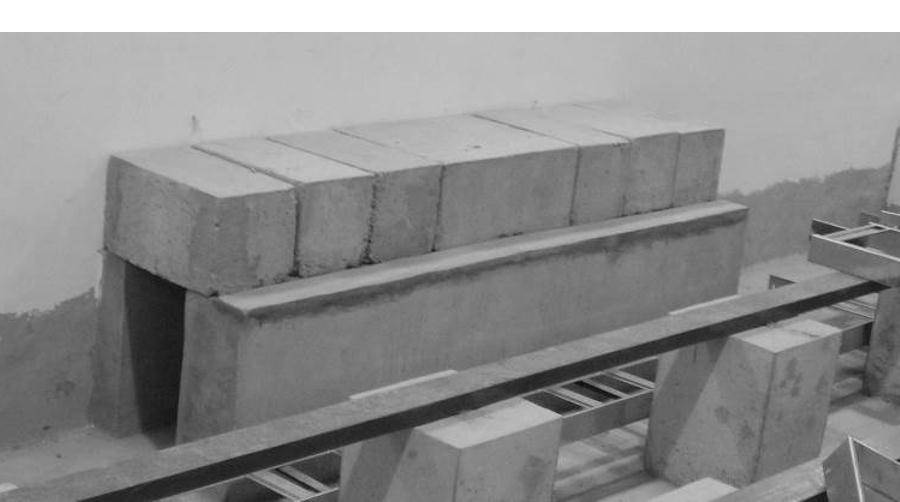
It is inevitable to set some cable holes for the massive control/power cables entering into the tunnel. According to traditional methodology, the 'U’ structure or several-legs structure is often used for preventing the radiation leakage[5]. But the actual situation is that several straight holes connecting the tunnel floor and power supply hall floor, so an additional shielding block has been designed in order to turn the straight holes into a simple 'T’ model maze structure as shown in Fig. 6. The mixed radiation field outside the cable hole, represented by the third cable hole downside the Fig. 1, is mainly dominated by neutron according to the calculation shown in Fig. 7, meantime, which corresponds to the maximum dose rate during all the cable holes. Concrete has been chosen as the material for shielding blocks for its good shielding effect for neutron and gamma shielding, and the built concrete shielding block has been shown in Fig. 8. In practice, the remaining space in the cable holes, after laying the cables, will be jammed with polythene particles in order to minimize the neutron radiation.

D. Design for the shielding door
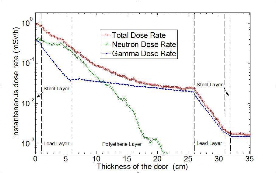
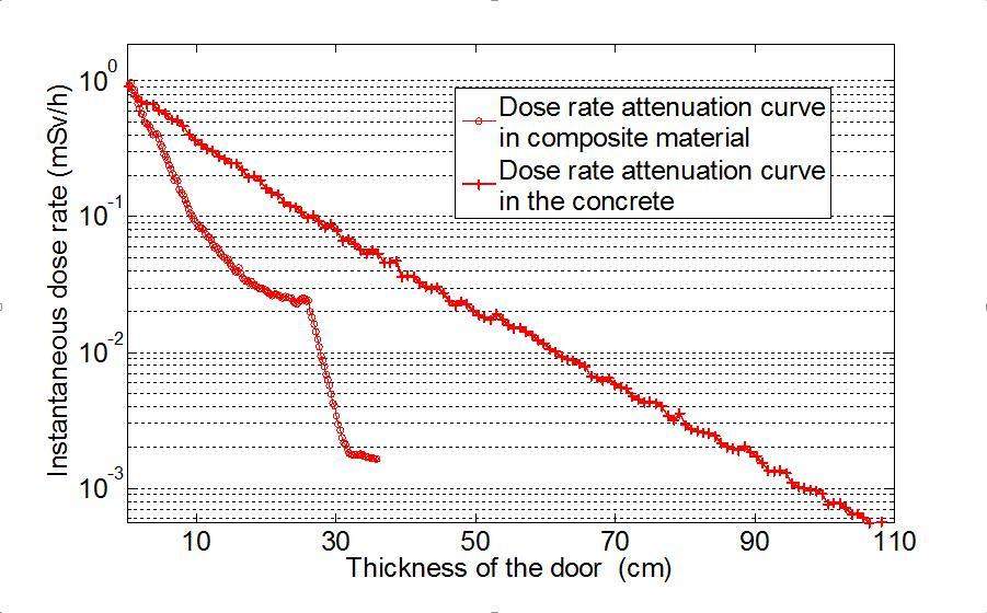
It is convenient to set a passageway for equipment maintenance access or devices transportation as shown in Fig. 1, where there is a new east door. In order to ensure the door’s sufficient shielding effect, which should almost equal to adjacent wall meanwhile minimize its thickness, a kind of shielding door made by composite material (5 cm Lead + 20 cm PE + 5 cm Lead, surrounded by 1 cm steel outside both sides) is proposed. Fig. 9 shows the radiation attenuation curve while the radiation transfers through the door. From the figure we can predict that the gamma dose rate drop sharply in the outer lead layer while the neutron dose rate almost maintain a stable level. The situation is just the opposite while the inner is polythene layer. This is consistent with theoretical analysis, also, the gamma attenuation curve in the lead material agrees with the attenuation coefficient listed in [6]. Through this method, a thinner shielding door, whose thickness is only 32 cm, was designed. We believe that the radiation shielding effect will equal to the effect of 90 cm thickness concrete as shown in Fig. 10.
IV. CONCLUSIONS
The main considerations related to radiation shielding for building a new accelerator in an existing tunnel were discussed in this paper. A detailed shielding design process is discussed for verifying and reinforcing the shielding structure of the tunnel. According to the beam loss parameters and the existing situation of the tunnel, variety of radiation shielding structures are designed, such as the local shielding design, the additional 'T’ structure shielding design and the composite material applying. In addition, for some areas with weak shielding structure additional local shielding space needs to be reserved.

