I. INTRODUCTION
In recent years, neutrons have been studied for application in various fields, such as material analysis and boron neutron capture therapy. To create a compact shield for such facilities, a neutron shield concrete that has the same mechanical strength as ordinary concrete has been developed [1]. This concrete contains about 15 wt% of hydrogen and about 3 wt% of B2O3.
It is important to verify the homogeneity of the boron and hydrogen content in the concrete to ensure adequate shielding performance. Therefore, neutron radiography images of the concrete were taken using the Thermal Neutron Radiography Facility (TNRF) of the JRR-3M research reactor and the transmission ratio of the thermal neutrons was estimated.
Visualization of water penetration into concrete through cracks using neutron radiography was reported recently [2], but no application of visualization of homogeneity exists.
II. NEUTRON SHIELD CONCRETE
Neutron shield concrete uses colemanite and peridotite rocks as aggregates. Colemanite is a natural mineral that is rich in boron in the form of B2O3. Peridotite is a natural mineral that is rich in hydrogen atoms in the form of H2O. These aggregate materials, together with ordinary Portland cement, form concrete. Colemanite was used for 10 wt% of the concrete composition to improve the shielding performance and production of the concrete. The density of the neutron shield concrete is the same as that of ordinary concrete. Thus, the neutron shield concrete includes B2O3, which has a large capture cross section for thermal neutrons, and abundant H2O, which slows down neutrons around 2 MeV via elastic scattering. This shield concrete also contains more iron in the form of Fe2O3 than ordinary concrete, which slows down high-energy neutrons via inelastic scatterings. These effects provide the concrete with unique shielding performance. Table 1 shows the element analysis for the neutron shield concrete and the ordinary concrete, both of them have the same average density of 2.2 g/cm3.
| Neutron shield concrete (wt%) | ||||
| SiO2 | H2O | MgO | MnO | Al2O3 |
| 33.1 | 14.8 | 29.1 | 0.09 | 1.54 |
| CaO | SO3 | Cl | Cs | Na2O |
| 11 | 0.38 | 0.016 | <0.01 | 0.05 |
| TiO2 | B2O3 | P2O5 | Eu | CoO |
| 0.07 | 2.61 | 0.11 | <0.01 | <0.01 |
| Fe2O3 | K2O | Ig-loss | Density | |
| 6.23 | 0.06 | 13.6 | 2.2 g/cm3 | |
| Ordinary concrete (wt%) | ||||
| SiO2 | H2O | MgO | MnO | Al2O3 |
| 57.7 | 6.04 | 1.31 | 0.08 | 10.5 |
| CaO | Cs | Na2O | K2O | TiO2 |
| 14.5 | <0.01 | 2.29 | 0.86 | 0.39 |
| Fe2O3 | Eu | Co | Density | |
| 3.47 | <0.01 | <0.01 | 2.2 g/cm3 | |
III. NEUTRON RADIOGRAPHY
Neutron radiography, a non-destructive imaging technique that uses thermal neutrons, is a powerful tool for inspecting materials. The difference between the neutron and X-ray imaging techniques is that X-ray attenuation depends on atomic numbers, whereas neutron attenuation is different for each nucleus. Fig. 1 shows the attenuation coefficient for thermal neutrons [3].
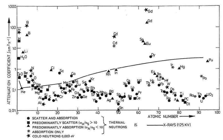
When the neutron beam irradiates a sample, the camera that is located behind the sample takes a picture with black and white contrast. Substantial attenuation of thermal neutrons in elements, such as hydrogen and boron, will cause these neutrons to appear shadowed in the radiographic image. Therefore, while water is not visible in X-ray imaging, it is clearly visible in neutron radiographs because of its high hydrogen content. As shown in Fig. 1, hydrogen, lithium, boron, etc. have a large attenuation ratio, whereas silicon, calcium, oxygen, aluminum, etc. have a small attenuation ratio.
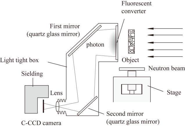
A thermal neutron beam can be found in a research reactor. The TNRF is installed at the JRR-3M research reactor of the Japan Atomic Energy Agency. Table 2 shows the specifications of the TNRF, and Fig. 2 shows its experimental system. In Fig. 2, the thermal neutron beam comes from the JRR-3M and impacts the object. The fluorescent converter is a combination of a scintillator and Gd or 6Li. When a thermal neutron is captured by Gd or 6Li, the scintillator fluoresces. The fluorescence is scattered by the mirror, and then a photograph or video image is taken with the cold CCD camera.
| Thermal neutron flux | 1.2×10⁸(n/cm2/s) |
| Irradiation area | 255 mmW×305 mmH |
| Resolution of cold-CCD | 100 μm/pixel |
| Fluorescent converter | Li-loaded ZnS scintillator |
IV. EXPERIMENT
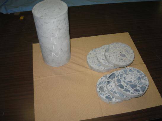
Ordinary concrete and neutron shield concrete were used as experimental samples. As shown in Fig. 3, 20 mm thick slices were obtained from a concrete sample of cylinder with ϕ100 mm (diameter), starting at the surface and proceeding to greater depths of the core sample, and used for the experiment.
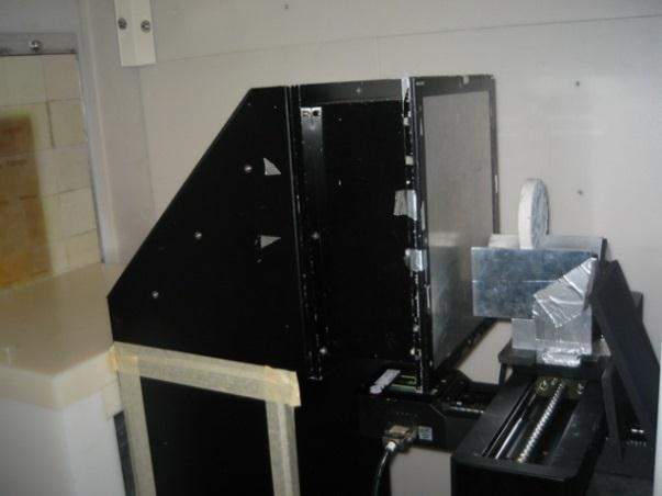
Each sample of sliced concrete was set in front of the fluorescent converter. The experimental setup is shown in Fig. 4.
V. RESULTS AND DISCUSSION
The intensity of the neutron beam that passes through the concrete sample is described by the following equation[4]:
where ∑ is the macroscopic cross section, t is the sample thickness, I is the intensity of the neutron beam that passes through the sample, and I0 is the incident intensity of the neutron beam.
The neutron radiography images and the respective transmission ratio of each, measured at a line through their centers, are shown in Fig. 5. In these images, the intensity of the neutrons appears as contrasting black and white. Thus, the intensity can be read as digital bit data. These images were produced from image processing software through digital bit analysis. A transmission ratio of 1.00 (white) means no shielding, while a ratio of 0.00 (black) means complete shielding.
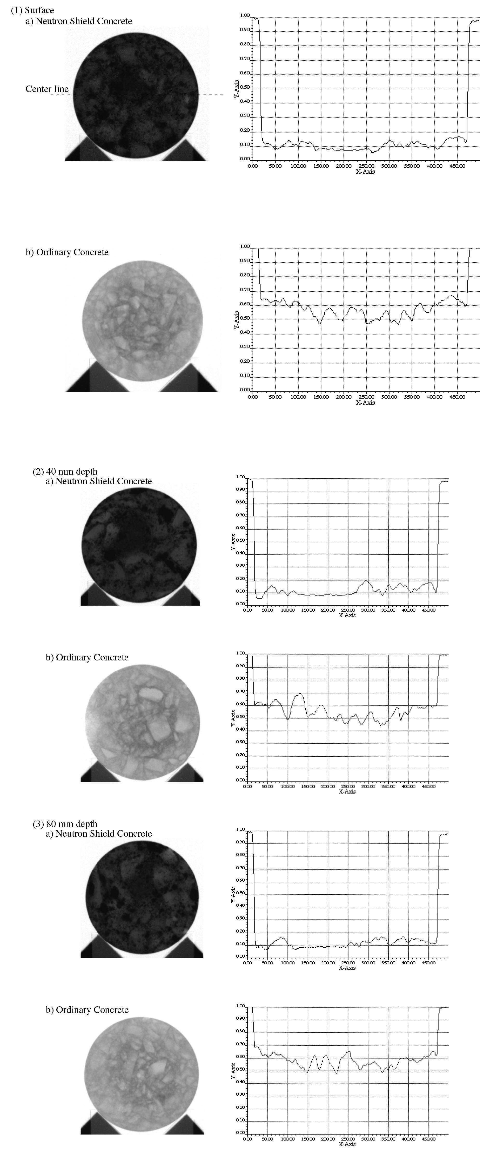
As shown in Fig. 5, the transmission ratio of each concrete sample was almost the same for each depth. No large frequency appears in the graph, which indicates good homogeneity at the center line and, thus, no breaks in the shielding. The transmission ratio of the neutron shield concrete is almost half that of the ordinary concrete, which indicates that the shielding performance is almost twice as good as that of ordinary concrete.
VI. CONCLUSION
Tests on the homogeneity of neutron shield concrete were performed using neutron radiography. The results showed that the transmission ratio of the concrete was almost the same at each depth. Thus, neutron radiography imaging is useful for this type of investigation.
The result of this study is still qualitative. Therefore, the future plan is to develop this study to perform quantitative analysis and accurate estimation.
Development of Novel Neutron Shielding Concrete
, Nucl Technol, 2009, 168: 545-552.Visualization of water penetration into concrete through cracks by neutron radiography
,Neutron Radiography: Equipment and Methods
, Atom. Energy Rev, 1977, 15: 169-220.
