Introduction:
The ultrahard X-ray multi-functional application (UXMA, also known as the BL12SW) beamline is a phase-II Beamline Project at the Shanghai Synchrotron Facility (SSRF) [1], which is a dedicated high-energy beamline. Its main objective was divided into two parts. One is the structural and microstructural characterization of engineering materials in near-real service environments or synthetic environments, and the other is high-temperature and high-pressure in-situ research related to earth sciences using a large-volume press (LVP) [2, 3]. Synchrotron radiation high-energy X-ray diffraction (HEXRD) [4] and imaging technology [5, 6] are some of most effective methods for characterizing engineering materials [7, 8]. For example, with the help of HEXRD, microstructure [9], grain growth [10], recrystallization [11, 12], texture development[12, 13], orientation gradients [14, 15], and additive manufacturing [16], as well as the real process of additive manufacturing [17] and failure in structural materials [18], can abe monitored by imaging technology. In-situ research on engineering materials in complex service environments can be achieved by equipping them with a series of in-situ devices [10], such as heat treatment [19], creep [20], fatigue [21, 22], thermomechanical fatigue [19], stress [11], strain distribution [23, 24], recrystallization [25], martensitic transition [26], and magnetic phase transition [27, 28]. Owing to the high-temperature and high-pressure conditions of most substances formed in the deep Earth, using high-temperature and high-pressure experimental instruments to simulate these conditions is an important means of understanding the material state and dynamic processes in the deep Earth [29, 30]. The in situ high-temperature and high-pressure experimental station, combined with synchrotron radiation characterization techniques, allows researchers to observe various dynamic processes of Earth materials in real time under in situ conditions, which is closer to the real state of the deep Earth [31, 32]. Therefore, exploring and understanding the causes of large-scale natural disasters, such as earthquakes and volcanoes, will be of great help to people [33].
Worldwide, there are many high-energy beamlines running either for Earth science using a large-volume press [34, 35] or for engineering materials [8]. However, no high-energy beamlines are currently in operation in China. The UXMA beamline features high energy, high flux, and a large beam spot combined with high-energy X-ray characterization techniques, making it particularly suitable for conducting in situ experiments. The beamline has four experimental hutches, two large volume press experimental hutches (LVP1 and LVP2), and two engineering material experimental hutches (ENG1 and ENG2). Each experimental hutch was equipped with a different in situ environment. For instance, the LVP1 and LVP2 are equipped with a 200-ton Deformation-DIA (a type of cubic anvil, known as DIA) press and a 2000-ton dual-mode (DDIA and Kawai) large press, respectively [2]. Combined with synchrotron characterization techniques such as energy dispersion X-ray diffraction (EDXRD), wide-angle X-ray diffraction (XRD), high-resolution imaging techniques, and ultrasound [36, 37], each press can carry out in situ high-pressure and high-temperature experiments up to tens of gigapascals and thousands of Kelvin, [34, 38] which makes the LVP stations the first comprehensive experimental stations in China can conduct in situ large-volume press experimental characterization. Both engineering-material experimental hutches (ENG1 and ENG2) were equipped with different in situ environments to completely explore the capability of high-energy X-rays. ENG1 and ENG2 aim to characterize samples using relatively small and oversized devices, respectively. Particularly, ENG2 has built an extreme heave load sample stage (2 ton) with 5-high precision axes, allowing for in situ characterization experiments with an oversized device using high-energy X-ray techniques, such as EDXRD, XRD, high-resolution/rapid computerized tomography (CT) imaging, and pair distribution function (PDF). Moreover, high-temperature and force-loading in-situ environments were provided. Therefore, the engineering experimental stations were the first dedicated experimental stations for engineering material research in China.
Since trial operations began in June 2023, BL12SW has established a large user community in materials science and processing, earth science, and physics. This will play an important role in helping researchers in these areas.
This paper reviews the UXMA beamline in terms of the beamline, experimental hutches, and experimental methods for the BL12SW at the SSRF.
Beamline
Beamline overview
A schematic of the beamline is shown in Fig. 1, and the key parameters of the beamline are listed in Table 1. The UXMA beamline provides high-energy X-rays in the range 30–162 keV. The beamline employs a superconducting wiggler as the light source to provide sufficient flux in the high-energy range, as shown in Fig. 1. After the front end, two optical hutches and two experimental hutches (LVP1 and ENG1) were placed inside the main building, whereas one optical hutch and two experimental hutches (LVP2 and ENG2) were built in the external building. A set of permanent low-energy filters was located closest to the front end, followed by a white beam slit used for downstream beam definition. After the slit, a series of movable middle energy filters were employed in front of the cryogenically cooled meridional bending double Laue monochromator (DLM). A dual-white/monochromatic beam slit was placed between the meridional bending DLM monochromator and the first experimental hutch, LVP1. The second experimental hutch, ENG1, was located next to LVP1.

| Parameters | Values |
|---|---|
| Source | Superconducting wiggler, 4.2 T, 48 mm periodicity |
| Beam acceptance (H×V) (mrad2) | 1.0 × 0.3 |
| Working energy range (keV) | 30 – 162 |
| Beam modes | White and monochromatic |
| Monochromator | Si (111) cryo-cooled meridional bending double Laue |
| Si (311) water-cooled sagittal bending double Laue | |
| Bandwidth | ~ 10-3 to ~10-4 adjustable |
| Beam size at LVP1 (mm2) | Max: 42×12.6 |
| Beam size at LVP2 (mm2) | Max: 110 ×12.6, Focused beam: 280 μm |
| Beam size at ENG1 (mm2) | Max: 48×14.4 |
| Beam size at ENG2 (mm2) | Max:100×30, Focused beam: 280 μm |
| Photon flux (LVP1,100keV@25 μmrad2@200mA ring current), (photons/s) | 1.4 × 10¹¹ |
After ENG1, the beam was guided to the third optical hutch in the external building through a long transfer pipe by crossing the perimeter of the main experimental hall. The third optical hutch contained a dual white/monochromatic beam slit, followed by a water-cooled sagittal bending double Laue monochromator. The last two experimental hutches are LVP2 and ENG2. All experimental hutches could be operated in monochromatic and white beam modes.
Light source
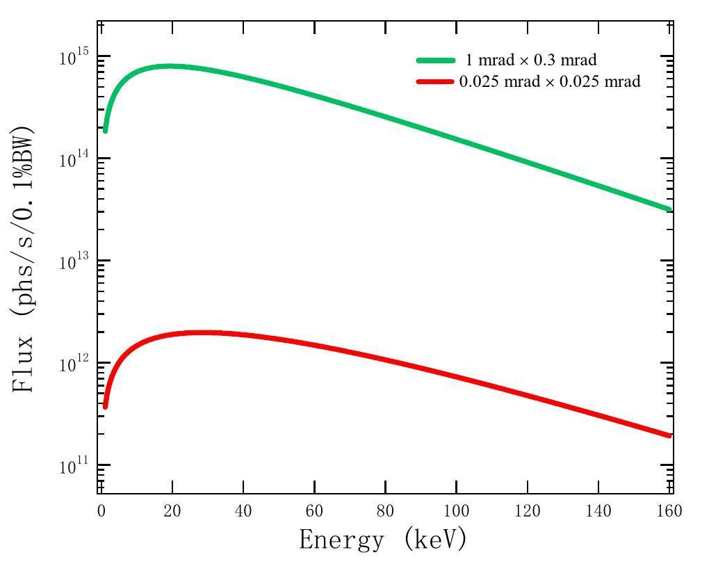
The Shanghai Light Source is a 3.5 GeV medium energy light source [1, 39]. To obtain sufficient flux of high-energy light from this light source, BL12SW uses a superconducting wiggler as an insertion device. The magnetic field of the insertion device was 4.2 T, and the number of its periods is 22.5. Each periodic length was 48 mm, and the total length of the insertion device was 1.08 m. The resulting deflection parameter K was 18.8, and the critical energy was 34.2 keV with a total power of 43.3 kW at a storage ring current of 300 mA, as listed in Table 2. This insertion device can provide X-rays with energies up to 160 keV with sufficient flux, as shown in Fig. 2. After the fixed front end aperture, an angular acceptance angle is 1.2 mrad horizontally and 0.3 mrad vertically; thus, the maximum heat load entering the beamline is 10.2 kW at 300 mA, making the heat load handling is extremely important for the beam design.
| Parameters | Values |
|---|---|
| Storage ring energy (GeV) | 3.5 |
| Nominal design current (mA) | 300 |
| Current (operation 2023) (mA) | 200 |
| Electron beam emittance (nm·rad) | 4.22 |
| Electron source size (μm) | 124.2 (σx), 10.33 (σy) |
| Electron source divergence (μrad) | 34.45 (σ'x), 4.125 (σ'y) |
| Insertion device | Superconducting wiggler |
| Magnetic field intensity, Bmax (T) | 4.2 |
| Number of periods | 22.5 |
| Periodic length (mm) | 48 |
| Critical energy (keV) | 34.2 |
| Kmax | 18.8 |
| Total power (kW) | 43.3 |
| Power density (kW/mrad2) | 45 |
Beamline optics
The first optical component after the front end was a high-heat-load, low-energy filter. The filter was placed 19 m away from the light source and consisted of two 1.5 mm CVD diamond discs to filter out low-energy X-rays below 15 keV. After these filters, a heat load of 4 kW was deducted from the downstream beam, which made this low-energy filter the first safety barrier to protect the downstream equipment. Each diamond filter has a thermal load of 2.1 kW; therefore, a highly effective water-cooling system is required to handle such a large amount of heat. To achieve this goal, the cooling system of the diamond filter adopts a complex spring-type cooling method, which not only increases the heat exchange efficiency significantly but also reduces the thermal stress generated at the welding seam when the diamond sheet is heated by a high-power white beam.
Three white beam slits were installed on the UXMA beamline. One was a dedicated white-light slit, whereas the other two were dual-white/monochromatic beam slits. The first white beam slit was placed 20 m from the light source, immediately after the low-energy diamond filter. This slit was the second safety barrier. It must be able to process all the thermal loads after the low-energy filters and define the divergence angle of the downstream beam. Hence, the maximum thermal load of this white beam slit1 was approximately 10.2 kW. The slit employs blades with an extended length and a much smaller bevel angle compared with a regular blade to process a large amount of heat. The length of the blade absorber was 550 mm and the beam-blocking surfaces had grazing incidence angles of approximately 2.08°. Seven water-cooled pipelines with inner diameters of 8 mm were placed on the receiving side of each absorber. A beam with a maximum size of 28 mm × 10 mm passed when the slits were fully opened. The second and third slits were white/monochromatic beam-compatible slits, which were installed in front of the two Laue monochromators, approximately 37 and 99 m away from the light source, respectively. Both slits were used to redefine the beam entering the monochromator. Water-cooling systems are also required, because both slits have a heat load of 2.8 kW. Moreover, these slits can be used as high-precision monochromatic slits to define the beam in the experimental hutches. Because of the 50 mm height offset between the white and monochromatic beams, each slit has very long vacuum-corrugated pipes, which makes both slits approximately 2-m long.
Due to the enormous heat load produced by the super conducting wiggler, heat load of 5.6 kW is still remained in the beam even after being tailored by the low-energy choppers and the white beam slits. Therefore, a set of medium-energy filters was installed in front of the monochromator to attenuate the thermal load and improve the monochromator performance. The filters consisted of two pieces of 4 mm SiC disc and four Cu discs of various thicknesses (1, 2, 4, and 8 mm). Each filter disk can move freely in and out of the beam and is driven by an independent motion mechanism. Notably, the filters can be utilized in different combinations, providing users with a great deal of freedom in designing their experiments. Owing to the large thermal load on each filter (SiC: 2.76 kW, 1 mm Cu: 2.12 kW, 2 mm Cu: 2.32 kW, 4 mm Cu: 2.62 kW, 8 mm Cu: 2.78 kW), each filter was cooled using an independent water-cooling system with separate copper pipes twining around the discs.
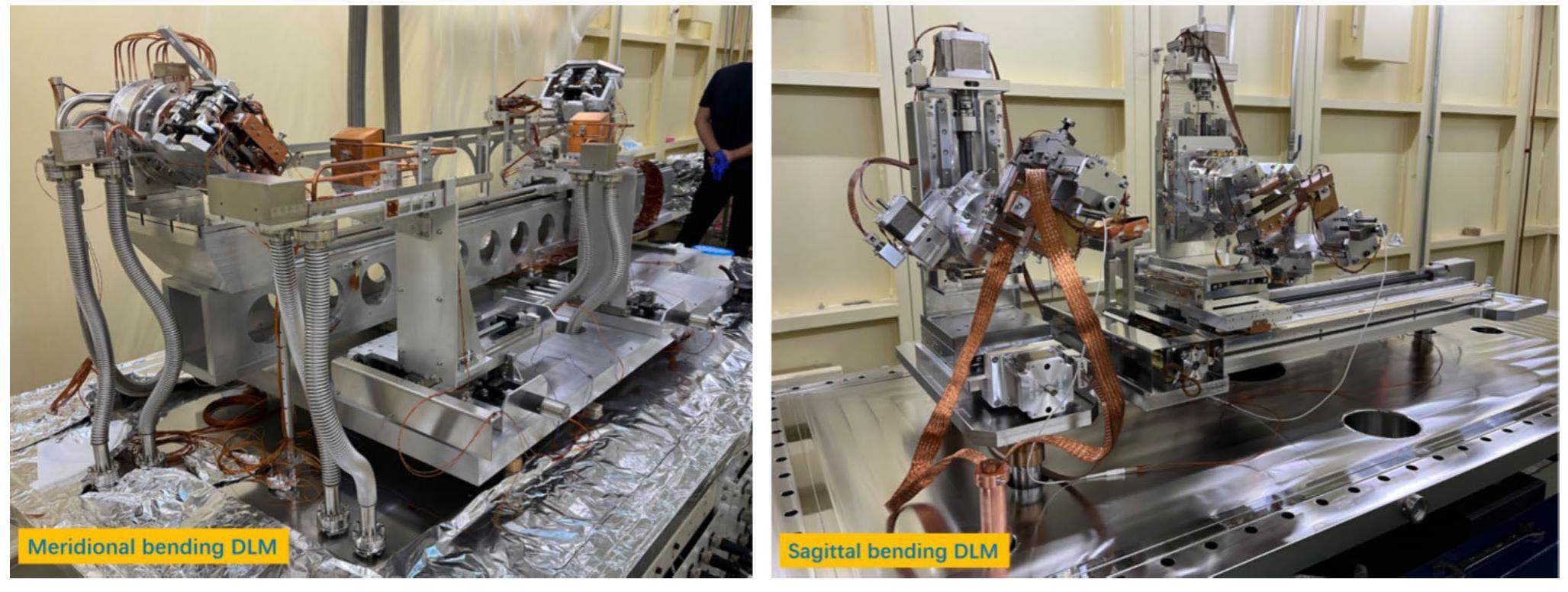
The UXMA beamline adopted a dual-monochromator design for various research purposes. A liquid nitrogen-cooled meridional bending double Laue monochromator (MBDLM) (left figure in Fig. 3) and a sagittal bending double Laue monochromator (SBDLM) (right figure in Fig. 3) were installed 34 and 100 m away from the light source, respectively. Table 3 lists the key parameters of both monochromators. The MBDLM can effectively collect a beam with large acceptance angle of 1.0 mrad × 0.3 mrad. The monochromator used a pair of Si (111) crystals with an asymmetric angle of 45°, which were placed in the Laue pattern. The Silicon crystal was 4-mm thick and cut into an H-shape. A pair of high-precision piezoelectric actuators was used to dynamically bend the crystal in the meridian direction, resulting in a monochromator with a wide and adjustable bandwidth. Therefore, the flux in the high-energy range can be significantly increased in comparison to that of a flat Si crystal monochromator. The heat load on the first crystal was as high as 840 W; therefore, liquid-nitrogen cooling was necessary to keep the monochromator safe and functional. This monochromator can provide a monochromatic beam with an energy resolution of 10-3–10-4 over a wide energy range of 30–160 keV, which can provide a large beam size of 100 mm at 100 m away from the source. Notably, the stability of this monochromator was high, making it suitable for high-energy large-view imaging. This monochromator was located in front of all the experimental hutches; therefore, all hutches could be used.
| Meridional bending DLM | Sagittal bending DLM | |
|---|---|---|
| Location (m) | 34 | 100 |
| Energy range (keV) | 30-162 | 60-120 |
| Crystal | Si (111) | Si (311) |
| Incidence angle (mrad2) | 1.0×0.3 | 0.3×0.03 |
| Asymmetric cutting angle (°) | 45 | 64.76 |
| Thickness (mm) | 4 | 1 |
| Bending radius (m) | 46–49 | 1 - 3 |
| Energy resolution | 10-4 - 10-3 | 10-3 |
| Beam size | 280μm - 100mm@sample@ENG2 | 280 μm @ sample |
| Cooling system | Liquid nitrogen-cooling system | Water-cooling system |
The second monochromator was a water-cooled sagittal bending double Laue monochromator [40] placed in an external building outside the main building to produce a focused high-energy beam. It covers an energy range of 60–120 keV and can effectively collect a beam of 0.3 mrad. The monochromator adopts two 1-mm thick asymmetrically cut Si (311) crystals with an asymmetrical angle of 64.76° arranged in the Laue mode as the MBDLM. The crystals were bent in the sagittal direction using a leaf spring-bending mechanism to achieve horizontal focusing. A focused beam of 280 μm was obtained at the sample spot in the energy range 60–120 keV, significantly increasing the flux density at the sample by two orders of magnitude. In addition, because UXMA can be operated in both white and monochromatic beam modes, both monochromators can be moved out of the beam path to allow the full white beam to pass through.
Experimental stations
Large volume press (LVP) stations
200-ton large volume press station 1 (LVP1)
As shown in Fig. 4, the 200 ton large-volume press station LVP1 contains a 200-ton DDIA large volume press (LPO 200-300/70, manufactured by Max Voggenreiter) and a multimode detector switching platform. The main ram of the 200-ton DDIA LVP has a maximum load of 200 t with a full stroke of 70 mm. The DDIA module’s differential ram stroke is -1 mm to + 4 mm. Three different modes of compression were utilized for specific experimental purposes. The first was called cubic DIA compression with six first-stage anvils. The edge sizes of the anvils were either 6 or 3 mm. The second mode is cubic 6-6 compression [41] with first-stage anvils having a 27-mm edge. Both isotropic and anisotropic compression experiments were conducted in these two modes. The third mode is conventional 6-8 compression with first-stage anvils of 27 mm edge and second-stage anvils of 14 mm edge. Normally, a pressure of approximately 10 GPa is generated by this 200-ton LVP. Higher pressures of up to 20 GPa can be achieved by employing sintered diamond as the second-stage anvil.
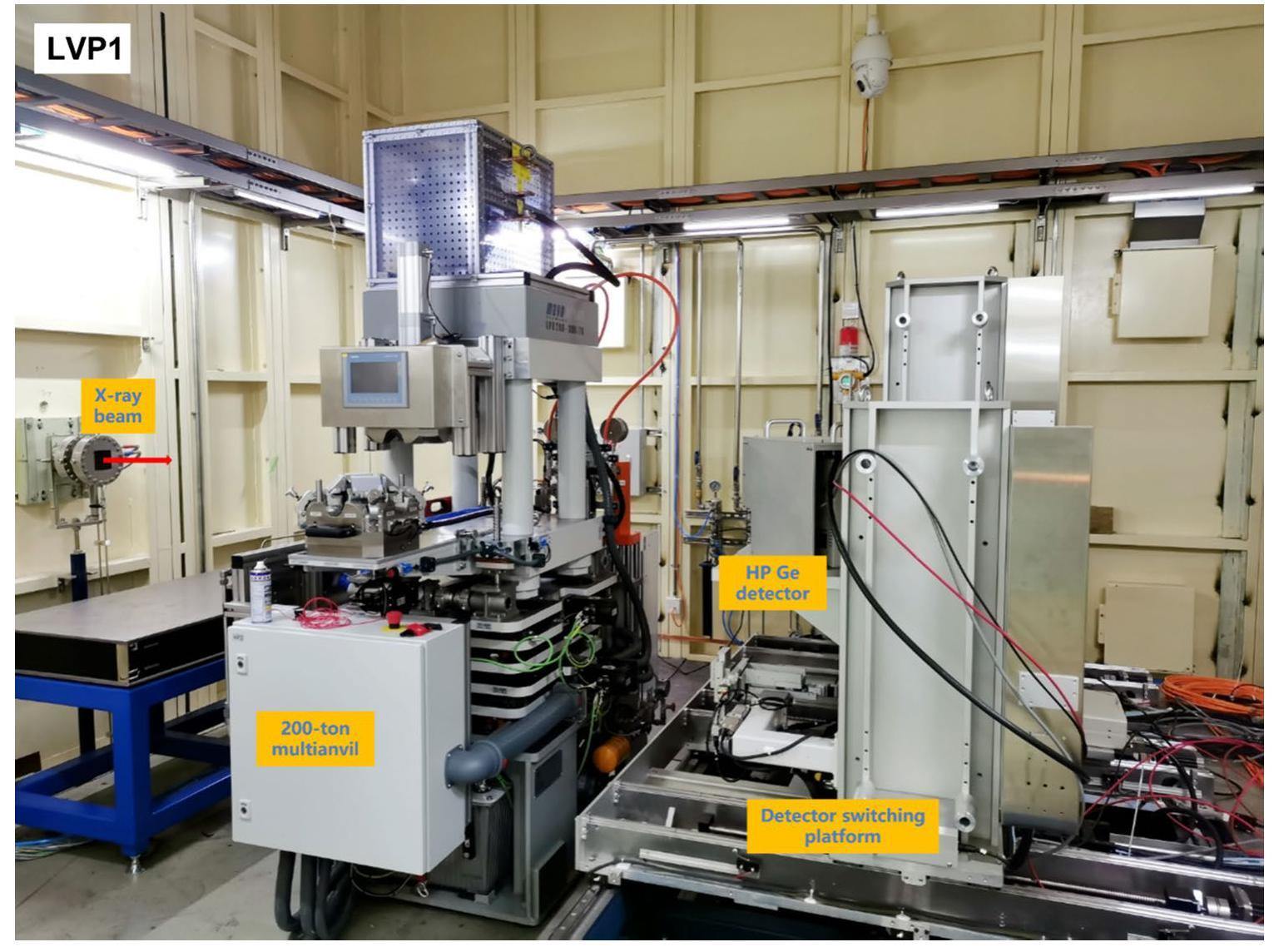
A multi-axis alignment stage was installed under the press to align the sample with the X-ray beam. The stage has six high-precision axes. The top three axes, Z1 (vertical), X1 (perpendicular to the X-ray beam), and Y1 (parallel to the X-ray beam), translate the sample into the ideal “gauge volume” position, which refers to the joint region through which incident and diffracted X-rays pass. Then, the C1 axis is rotated around the vertical axis. A set of axes X2 and Y2 located at the bottom moves the rotational C1 axis/sample center further to the target position; therefore, users can keep the sample in the same position in the beam when rotating the sample. The translation ranges of all the X1, Y1, X2, and Y2 axes are ± 10 mm. This LVP is designed to be white/monochromatic beam compatible; therefore, the vertical range of the Z1 axis is - 20 mm to + 80 mm to overcome the 50 mm height offset between the white beam and the monochromatic beam. The travel range of the rotational C1 axis is ± 10°.
This LVP can provide in situ high-temperature conditions during compression and decompression cycles. A heating system was installed in a 200-ton multianvil equipped with 3 kW AC power and five alternative outputs: 5V/600A, 7.5V/400A, 10V/300A, 15V/200A, and 40V/75A. The sample temperature was expected to reach 2000 K, depending on the heater material. Ultrasound measurements can also be performed as required.
Energy-dispersive X-ray diffraction (ED-XRD) and high-energy imaging were available in LVP1 for sample characterization under high pressure and high-temperature conditions. For EDXRD, a mirror (Canberra) high-purity germanium solid-state detector (Ge-SSD) is installed on a detector switching platform. In situ sample/cell images were obtained using an Optique Peter X-ray microscope. High-energy imaging can also be performed using the same X-ray microscope if necessary. These characterization techniques are switchable according to the demand. In this hutch, the “gauge volume/length” are approximately 1 to 2 mm determined by the geometry of the collimator system and incident beam size. 2θ diffraction angle of approximately 6° and incident beam size of 100 μm are used.
2000 ton large volume press station 2 (LVP2)
The LVP2 experimental hutch was located in the external building of BL12SW. A 2000-ton multi-anvil apparatus (LPO 2000-710/80, manufactured by Max Voggenreiter) is installed with dual DDIA and Kawai modules, as shown in Figs. 5 and 6. The maximum load of the main ram was 2000 ton with a full stroke of 80 mm. The DDIA module’s differential ram stroke is -10 mm to +10 mm. The displacements of the two vertical differentials and the four equatorial anvils were measured individually using stroke gauges. The DDIA and Kawai modules are interchangeable and automatically driven by a bus carrier. The upper blocks of both modules were lifted using a gas-driven self-lifting unit. The sample with the lower block was moved further toward the final load position of the rail for recovery.
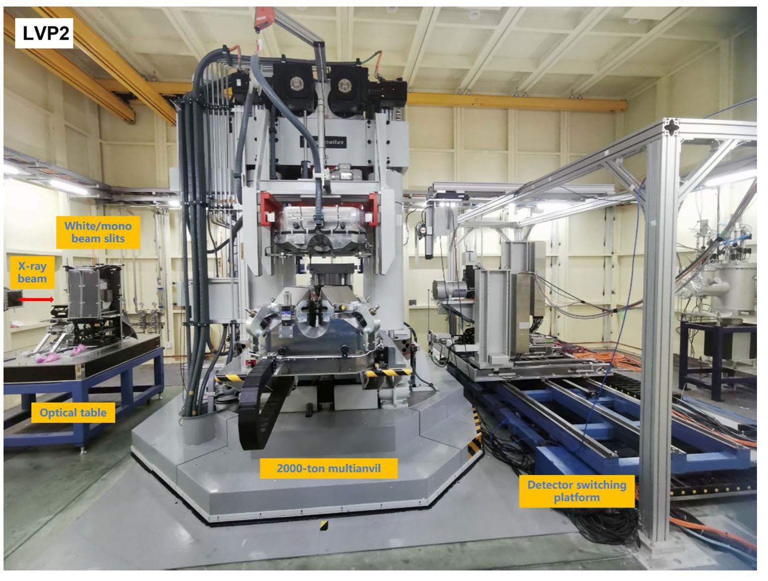
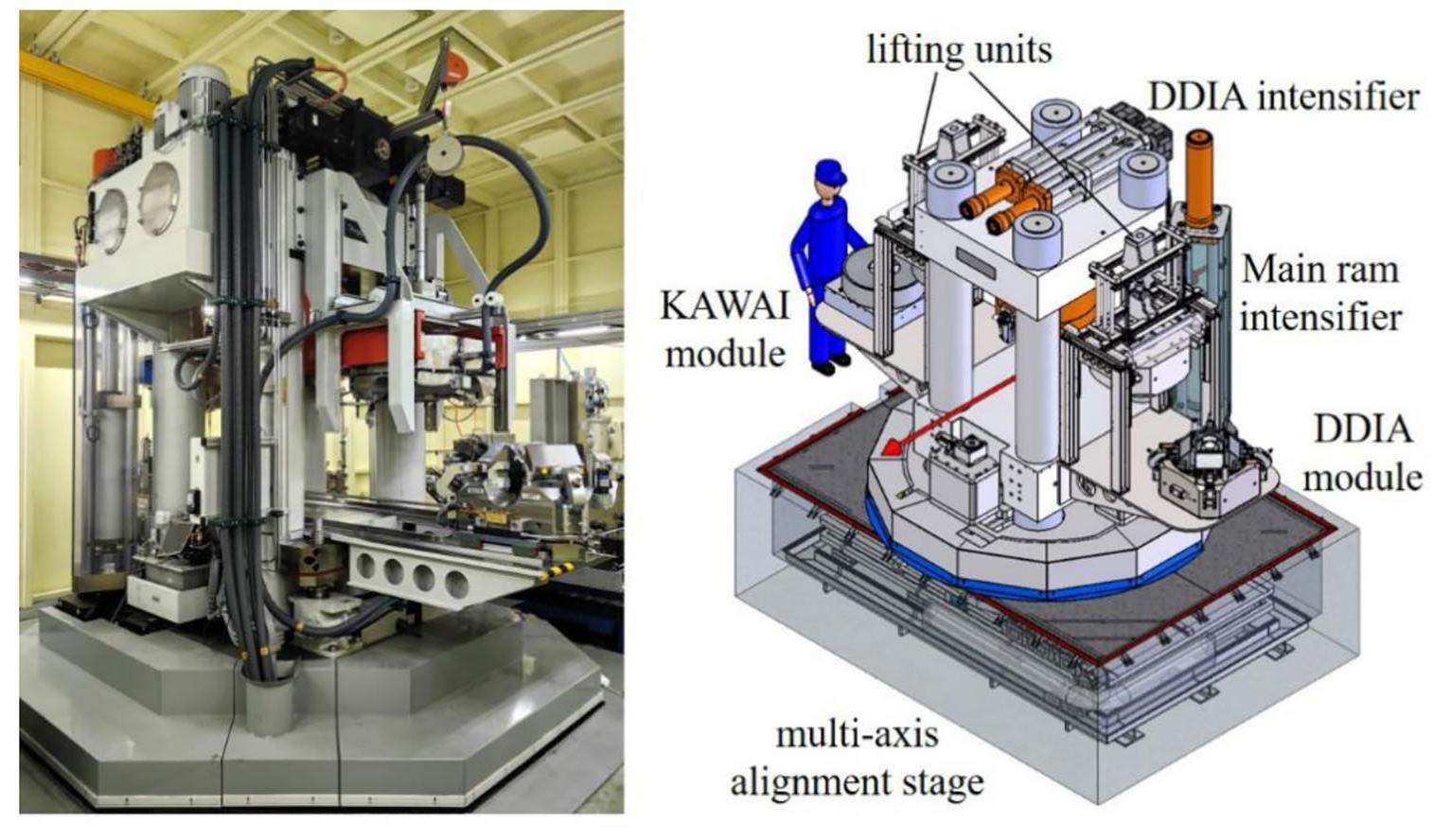
For the Kawai module, a typical 6-8 cell assembly with 1 inch second stage anvils was utilized for the high-pressure experiment. Two types of first-stage anvils in the DDIA module are available to users. One is the tungsten carbide anvils with an edge size of 27 mm designed for the 6-6 cell assemble as well as the 6-8 assemble with which isotropic compression and deformation experiments can also be performed. The other type is the conventional 49 mm first stage steel anvils designed for 6-8 assembly with 1 inch second stage anvils. For the ultra-high-pressure experiments, sintered diamond anvils with an edge size of 14 mm were also available, if needed. With a careful design, a sample pressure of up to 35 GPa can be achieved.
A multi-axis alignment stage, similar to that of 200-ton multianvil is installed in a 3 m × 4 m pit underneath, playing a role in supporting and adjusting the sample position. This stage consisted of six axes. The travel ranges of all the translation X1, Y1, X2, and Y2 axes are ± 50 mm. The vertical travel range of Z1 axis is - 20 mm to + 80 mm, and the rotational range of C1 axis is ± 15°.
In-situ high-temperature conditions are available for the 2000-ton LVP. Its heating system has 6 kW AC power and five alternative outputs: 8 V/750 A, 15 V/400 A, 20 V/300 A, 30 V/200 A, and 50 V/120 A. The highest sample temperature was expected to reach 2100 K, depending on the heater material.
EDXRD and high-energy imaging are also available for LVP2, and the setup is similar to that for LVP1. Additionally, angle dispersive X-ray diffraction (ADXRD) experiments can be performed with a Rayonix SX165 CCD detector (pixel array 2048 × 2048, pixel size 80 μm, 16-bit image), if sintered diamond second stage anvils are employed. A portable 17-inch iRay Mercu 1717V (pixel array 3072 × 3072, pixel size 139 μm, 16-bit image) image plate is available.
Engineering application stations
Engineering materials station 1
Engineering material station 1 (ENG1) is located in the main building next to LVP1 station. This station is especially designed for experiments on millimeter-scale samples and small in-situ devices. Figure 7 shows the setup of the end station. The station was equipped with a high-precision nine-axis sample stage for diffraction and imaging, which consisted mainly of a 5-axis bottom stage and a removable air-bearing rotation stage (3-axis). The bottom sample stage had a vertical adjustment axis (Z1), a 360° rotation angle (Phi), two tilt axes (X-tilt and Y-tilt), and a long translation axis (X). The air-bearing stage contains a vertical adjustment axis (Z2), two position-adjustment axes (X2 and Y2), and a continuous gas-driven rotation axis. The maximum rotation speed of the air-bearing stage was 200 rpm, which was suitable for rapid CT experiments. The maximum load capacity of the bottom sample stage was 200 kg and that of the air-bearing high-speed stage was 50 kg in the static state.
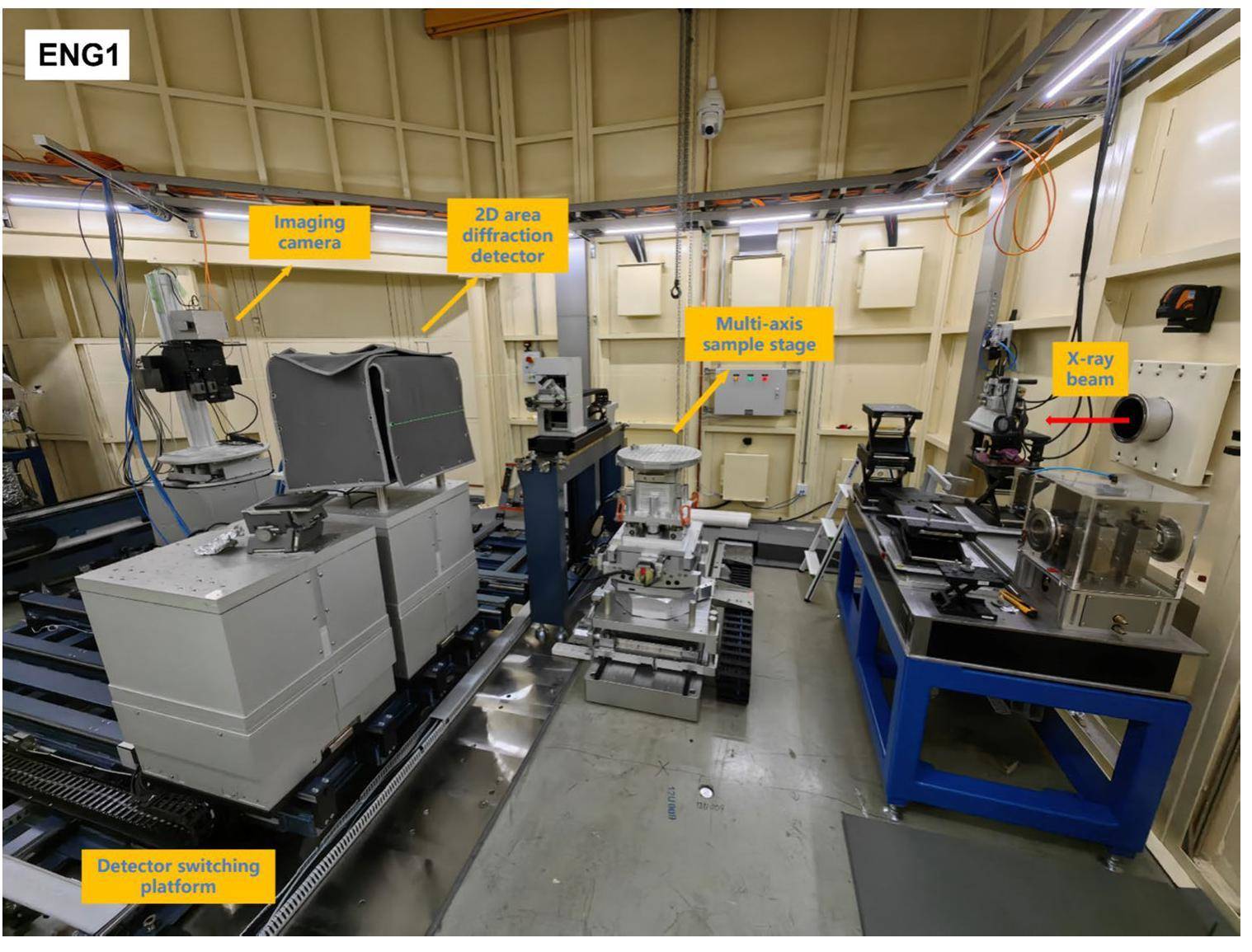
A detector-switching platform is installed adjacent to the sample stage to support the detector. The platform consists of five modules. Each module has independently driven mechanisms, allowing detectors to move along the beam direction over a long range of 2 m and switch between different detectors based on different experimental methods. A Pilatus 3X CdTe 2M diffraction detector and a multi-module imaging system are currently equipped in ENG1 to carry out high-energy XRD, PDF, 2D imaging, and CT. The imaging system consists of two fixed-magnification modules and one zoom module. The magnifications were 2 ×, 7.5 ×, and 0.28 - 1.8 ×, respectively. The best resolution of imaging system achieved is approximately 2 µm with the PCO edge 5.5 CMOS (6.5 µm per pixel). Moreover, a FASTCAM Mini UX100 high-speed camera was used for high-speed imaging. Spare detector modules are reserved for upgrading potential experimental methods. The peak at the end of the hutch can be utilized for large-angle diffraction and phase-contrast imaging.
Engineering materials station 2
Engineering materials station 2 (ENG2)(as shown in Fig. 8) is located at the end of the beamline and is specially designed for experiments on oversized samples (up to 2 tons in weight) and in situ equipment. The size of this hutch was 11 m × 7 m × 5 m with a 3-ton electronic crane, making it convenient for the entry and exit of large equipment. A specially designed sample stage was installed 3m below ground level. The maximum load-bearing capacity of this stage was 2 t, and its top surface was almost flush with the ground at the lowest position, leaving enough space for large industrial samples and in situ equipment in real service environments. Notably, this stage has a 5 axes high precision adjustment mechanism. The vertical Z-axis allows the stage to move up to 1 m, making it extremely friendly for in situ experiments with the help of high-energy characterization techniques.
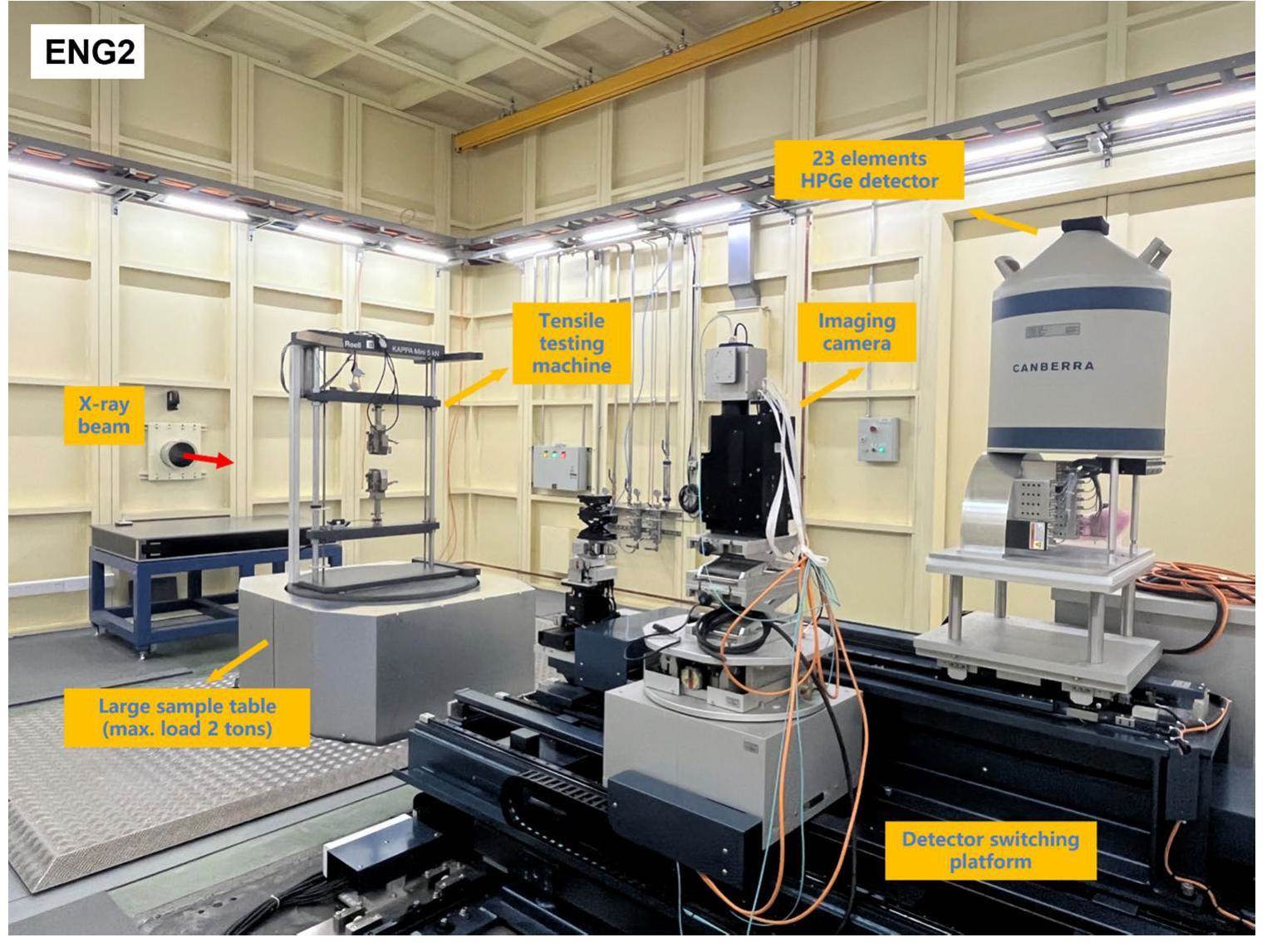
ENG2 had a detector-switching platform similar to that of ENG1. It has four modules that support the detectors. The function of this platform is the same as that of ENG1. However, this hutch is equipped with a 23-elements high purity germanium detector, which is utilized for energy-dispersive diffraction. A complex two-slit collimation system is also added to the detector to increase its resolution; therefore, a 23-element high-purity germanium detector can be employed to detect the internal stress distribution and strain tensor of the materials. Moreover, a large field-of-view imaging system with a 100-mm FOV is planned for installation in this hutch for upgrading.
Commissioning results
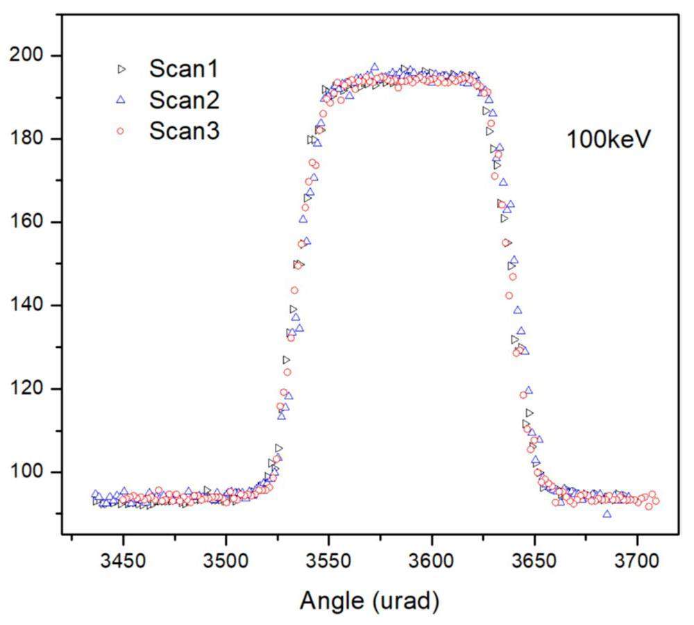
The energy resolution of the beamline depends on the vertical divergence angle of the incident beam and Darwin width of the monochromator crystal. The bandwidth effect of the flat crystal Si (111) can be neglected since the bandwidth of the Laue monochromator of the UXMA beamline is at the 10-3 level, which is several tens of times larger than the energy resolution of 10-4 for a flat crystal Si(111). The resolution was obtained by scanning the rocking curve of the Laue monochromator using a flat Si(111) crystal as the analysis crystal [41]. The calculation formula is:
The Bragg angle of Si (111) at 100 keV is 1.132°. The rocking curve of the monochromator at 100 keV was measured and repeated three times. The results of the three scans are 100.2, 97.0, and 98.1 μrad, respectively, which is shown in Figure 9. Therefore, the average result of the three scans is 98.4 ± 1.4 μrad. Then, the energy resolution at 100 keV is calculated as (5.0 ± 0.1) × 10-3.
The photon flux was measured using a 500-mm long ionization chamber. The divergence of X-rays in the flux test is limited to 25 µrad by a monochromatic high precision slit. The absorption rate of normal filling gases, such as nitrogen, is considerably low to be utilized for photon flux determination of high-energy X-rays at 100 keV. Therefore, the ionization chamber was filled with high-Z xenon gas at a pressure of one atmosphere to increase the number of excited electrons. The high-order harmonics of 100 keV were above 200 keV, and their flux was one order of magnitude lower than that of 100 keV. The absorption rate of Xe gas at energies above 200 keV was less than 8%. Therefore, the influence of high-order harmonics on the measured flux was less than 2%. The number of X-ray photons absorbed by the ionization chamber N is determined by the incident photon flux N0, the absorption coefficient of the gas for X-ray photons μ, and the length of the ionization chamber's plates x using Eq. (1).
The intensity of the current I is determined by the absorbed number of photons N, the energy of the photons E, the average ionization energy of the gas molecules ε (for Xenon, ε ~ 22 eV), and the charge e by Eqs. (2) and (3).
The value of e-μx is calculated using the XOP software to obtain the transmission rate of X-rays in Xenon at the specific energy. If the operation beam current is not 300 mA, the flux at 300 mA can be converted using the following equation: N0(300 mA) = N0 (beam current) × 300 mA/beam current.
During the test, the ionization chamber voltage was set to 3000 V from 0 V stepwise to ensure that it operated in its working range. The current readings of the ion chamber for three times were 37.701, 37.805, and 37.650 µA, respectively, resulting in an average value of (37.719 ± 0.085) µA. The ionization energy of Xe gas was 22 eV. The absorption coefficient of X-rays in 500 mm Xe gas is approximately 0.368; hence, the flux at 200 mA can be obtained using equation (4).
Then a flux of (2.12±0.04) × 1011 phs/s is obtained at 100 keV with a divergence angle of 25 µrad at 300 mA.
Summary
The UXMA adopts a one-beamline and four-station design, including two engineering material experimental stations and two LVP experimental stations, aiming at in situ research on engineering materials and LVP-based high-pressure research. A superconducting wiggler was utilized as a light source to provide high energy with high flux. For the beamline, a two-high-energy Laue monochromator setup was adopted to meet different beam requirements. The liquid nitrogen cooled meridional bending Laue monochromator offers adjustable monochromatic beam in the energy range of 30–160 keV with adjustable bandwidth and high stability, while the water-cooled sagittal bending Laue monochromator could focus the beam horizontally, with a focused spot size of approximately 300 um. Both monochromators can achieve an energy resolution in the order of 10-3.
Four experimental hutches were constructed and used for various purposes. ENG1 is mainly aimed at small in-situ equipment with rapid, high-sensitivity, high-energy diffraction, and imaging techniques. ENG2 can perform in situ experiments using oversized in situ equipment with a large field of view and high-resolution imaging experiments. This station was also equipped with a 23-element energy-dispersive diffraction system. LVP1 and LVP2 were equipped with 200-ton and 2000-ton large volume press, respectively. The 200-ton press primarily adopts a one-stage pressure system, while the 2000-ton press adopts a two-stage pressure system that can support both the DDIA and KAWAI modules. Both LVP stations could perform high-temperature experiments and ultrasonic measurements. X-ray characterization techniques available for LVP end stations include energy-dispersive diffraction, XRD, and imaging.
Shanghai synchrotron radiation facility
. Natl. Sci. Rev. 1, 171-172 (2014). https://doi.org/10.1093/nsr/nwt039.Multi-anvil, high pressure apparatus: a half-century of development and progress
. High Pressure Res. 31, 493-532 (2011).https://doi.org/10.1080/08957959.2011.618698.Recent advances of high-pressure generation in a multianvil apparatus using sintered diamond anvils
. Geosci. Front. 2, 101-106 (2011). https://doi.org/10.1016/j.gsf.2010.09.005.High-Energy Synchrotron X-Ray Diffraction and Its Application to In Situ Structural Phase-Transition Studies in Complex Sample Environments
. JOM 64, 140-149 (2012). https://doi.org/10.1007/s11837-011-0218-8.Phase imaging using highly coherent X-rays: radiography, tomography, diffraction topography
. J. Synchrotron Radiat. 7, 196-201 (2000). https://doi.org/10.1107/S0909049500002995.Latest advances of X-ray imaging and biomedical applications beamline at SSRF
. Nucl. Sci. Tech. 26, 020102 (2015). https://doi.org/10.13538/j.1001-8042/nst.26.020102.High-Energy X-Ray Diffraction Microscopy in Materials Science
. Annu. Rev. 50, 395-436 (2020). https://doi.org/10.1146/annurev-matsci-070616-124125.I12: the Joint Engineering, Environment and Processing (JEEP) beamline at Diamond Light Source
. J. Synchrotron Radiat. 22, 828-838 (2015).https://doi.org/10.1107/S1600577515003513.An in situ high-energy X-ray diffraction study of micromechanical behavior of multiple phases in advanced high-strength steels
. Acta Mater. 57, 3965-3977 (2009). https://doi.org/10.1016/j.actamat.2009.05.002.High-pressure x-ray tomography microscope: Synchrotron computed microtomography at high pressure and temperature
. Rev. Sci. Instrum. (2005). https://doi.org/10.1063/1.1979477.Unprecedented non-hysteretic superelasticity of [001]-oriented NiCoFeGa single crystals
. Nat. Mater. 19, 712-718 (2020). https://doi.org/10.1038/s41563-020-0645-4.Dendritic crystallization in hydrous basaltic magmas controls magma mobility within the Earth’s crust
. Nat. Commun. 13, 3354 (2022). https://doi.org/10.1038/s41467-022-30890-8.Micromechanical behavior and texture evolution of duplex stainless steel studied by neutron diffraction and self-consistent modeling
. Acta Mater. 56, 782-793 (2008). https://doi.org/10.1016/j.actamat.2007.10.040.Unraveling submicron-scale mechanical heterogeneity by three-dimensional X-ray microdiffraction
. PNAS 115, 483-488 (2018). https://doi.org/10.1073/pnas.1711994115.Stress-induced reorientation of hydrides in Zr-1Nb-0.01Cu cladding tube studied by synchrotron X-ray diffraction and EBSD
. J. Nucl. Mater. 558, 153374 (2022). https://doi.org/10.1016/j.jnucmat.2021.153374.Ultrafine eutectic Ti-Fe-based alloys processed by additive manufacturing – A new candidate for high temperature applications
. Appl. Mater. Today 20, 100767 (2020). https://doi.org/10.1016/j.apmt.2020.100767.Application of Synchrotron X-Ray Imaging and Diffraction in Additive Manufacturing: A Review
. Acta Metall. Sin. 35, 25-48 (2022). https://doi.org/10.1007/s40195-021-01326-x.The imaging of failure in structural materials by synchrotron radiation X-ray microtomography
. Eng. Fract. Mech. 182, 127-156 (2017). https://doi.org/10.1016/j.engfracmech.2017.07.027.Thermomechanical fatigue behaviors and failure mechanism of 2.5D shallow curve-link-shaped woven composites
. Compos. Struct. 284, 115080 (2022). https://doi.org/10.1016/j.compstruct.2021.115080.On the microstructural origin of premature failure of creep strength enhanced martensitic steels
. J. Mater. Sci. Technol. 87, 269-279 (2021). https://doi.org/10.1016/j.jmst.2021.03.001.Experimental investigation and fatigue life prediction for 7475-T7351 aluminum alloy with and without shot peening-induced residual stresses
. Acta Mater. 59, 3737-3747 (2011). https://doi.org/10.1016/j.actamat.2011.03.013.Porosity induced fatigue damage of laser welded 7075-T6 joints investigated via synchrotron X-ray microtomography
. Sci. Technol. Weld. Join. 20, 11-19 (2015). https://doi.org/10.1179/1362171814Y.0000000249.Hoop Strain Measurement During a SiC/SiC Ceramic Composite Tube Burst Test by Digital Volume Correlation of X-Ray Computed Tomographs
. Exp. Mech. 63, 275-287 (2023). https://doi.org/10.1007/s11340-022-00916-9.In situ X-ray microdiffraction study of deformation-induced phase transformation in 304 austenitic stainless steel
. Acta Mater. 64, 12-23 (2014). https://doi.org/10.1016/j.actamat.2013.11.001.Recent progress on apparatus development and in situ observation of metal solidification processes via synchrotron radiation X-ray imaging: A review
. T. Nonferr. Metal Soc. 32, 2451-2479 (2022). https://doi.org/10.1016/S1003-6326(22)65959-4.New intrinsic mechanism on gum-like superelasticity of multifunctional alloys
. Sci. Rep. 3, 2156 (2013). https://doi.org/10.1038/srep02156.Magnetic field-assisted solidification of W319 Al alloy qualified by high-speed synchrotron tomography
. J. Alloys Comp. 938, 168691 (2023). https://doi.org/10.1016/j.jallcom.2022.168691.In situ high-energy X-ray studies of magnetic-field-induced phase transition in a ferromagnetic shape memory Ni–Co–Mn–In alloy
. Acta Mater. 56, 913-923 (2008). https://doi.org/10.1016/j.actamat.2007.10.045.Equation of state of γ-tricalcium phosphate, γ-Ca3(PO4)2, to lower mantle pressures
. Am. Mineral. 94, 1388-1391 (2009). https://doi.org/10.2138/am.2009.3160.Precise determination of phase relations in pyrolite across the 660km seismic discontinuity by in situ X-ray diffraction and quench experiments
. Phys. Earth Planet. Inter. 143-144, 185-199 (2004). https://doi.org/10.1016/j.pepi.2003.08.010.Trace element composition in tuite decomposed from natural apatite in high-pressure and high-temperature experiments
. Sci. China Earth Sci. 57, 2922-2927 (2014). https://doi.org/10.1007/s11430-014-4980-7.Transparent β-Si3N4 and γ-Si3N4 compacts synthesized with mixed-size precursor under high pressure and high temperature
. Appl. Phys. Lett. (2021). https://doi.org/10.1063/5.0070380.Sharp 660-km discontinuity controlled by extremely narrow binary post-spinel transition
. Nat. Geosci. 12, 869-872 (2019). https://doi.org/10.1038/s41561-019-0452-1.High-pressure science with a multi-anvil apparatus at SPring-8
. J. Phys.: Condens. Matter. 14, 10497 (2002). https://doi.org/10.1088/0953-8984/14/44/322.Extreme conditions research using the large-volume press at the P61B endstation, PETRA III
. J. Synchrotron Radiat. 29, 409-423 (2022).https://doi.org/10.1107/S1600577522001047.A system for measuring elastic wave velocity under high pressure and high temperature using a combination of ultrasonic measurement and the multi-anvil apparatus at SPring-8
. J. Synchrotron Radiat. 16, 762-768 (2009).https://doi.org/10.1107/S0909049509034980.Acoustic emission detection of micro-cracks under high pressure and high temperature in a deformation large-volume apparatus at the endstation P61B, PETRA III
. Rev. Sci. Instrum. (2023). https://doi.org/10.1063/5.0107630.A large-volume press facility at the Advanced Photon Source: diffraction and imaging studies on materials relevant to the cores of planetary bodies
. J. Phys.: Condens. Matt. 14, 11517 (2002). https://doi.org/10.1088/0953-8984/14/44/509.Current status and progresses of SSRF project
. Nucl. Sci. Tech. 19, 1-6 (2008). https://doi.org/10.1016/S1001-8042(08)60013-5.Sagittal focusing of high-energy synchrotron X-rays with asymmetric Laue crystals. I. Theoretical considerations
. J Appl. Crystall. 34, 504-509 (2001).https://doi.org/10.1107/S0021889801006409.Development of the Multi-anvil Assembly 6-6 for DIA and D-DIA type high-pressure apparatuses
. High Pressure Res. 28, 307-314 (2008). https://doi.org/10.1080/08957950802250607.The authors declare that they have no competing interests.

