Introduction
The Shanghai Synchrotron Radiation Facility (SSRF) is an intermediate-energy third-generation light source that provides a wide spectral range from the far-infrared to hard X-ray regions [1]. Currently, 15 beamlines are in operation at the SSRF. Only one of them is used for general diffraction experiments, namely, the diffraction beamline BL14B1 [2]. The X-ray diffraction (XRD) beamline (BL14B1) is one of the seven beamlines in Phase I at the SSRF and is based on a bending-magnet light source. BL14B1 is a general-purpose beamline for diffraction and is not optimized for surface and interface diffraction methods and technologies. Currently, specialized beamlines are not available to study these research domains.
The surfaces of solid materials, or the interfaces between two components, play a critical role in nearly every aspect of science and technology, particularly in nanomaterials, biomaterials, and modern semiconductors/electronics. The reduced size of low-dimensional devices can lead to new atomic rearrangements on the surfaces and interfaces, which in turn affect their physical, chemical, and electrical properties and behaviors. Detailed knowledge of the atomic rearrangements at the surface or interface is critical for a better understanding of their properties and to promote the development of novel and future devices. Therefore, it is important to obtain structural information on the surface and interface in various environments.
Surface XRD is a powerful technique for probing surface and interfacial structures [3-5]. It has two main advantages: the weak interaction of X-rays with matter allows for simple data analysis based on kinematic scattering theory, and X-rays offer a unique opportunity for accurate determination of the atomic structure at the atomic-scale level; the penetration of hard X-rays through matter means that various systems and environments, including liquid–liquid, liquid–solid, and solid–solid interfaces, can be studied, for which traditional electron and other scanning probes are not applicable. Moreover, the high credibility of this new beamline enables in-situ real-time investigations of thin-film growth mechanisms and allows molecular-scale studies of important chemical interactions at the interface.
To date, dedicated surface diffraction beamlines have been constructed in almost all third-generation synchrotron radiation facilities, such as the ESRF (ID03), APS (15-ID, 12-ID, 33-ID), SPring-8 (BL13XU), Diamond (I07), and Soleil (SIXS) [6-9]. However, there is currently no dedicated surface diffraction beamline available in China. To obtain the essential advantages of high collimation, high brightness, and low divergence angle that are required for diverse types of surface interface diffraction experiments, the BL02U2 beamline station was designed as one of the Phase Ⅱ beamlines at the SSRF, a third-generation light source with a 3.5-GeV storage ring and a 250 mA beam current. The BL02U2 beamline focuses on conducting surface and interface research on materials including low-dimensional thin films, atomic-scale structures of solid surfaces, solid–liquid and liquid–liquid interfaces, bio-membrane structures, and self-assembly in soft materials [10-12]
1) Surface and interface of low-dimensional thin films
Complex oxide materials can exhibit a variety of physical and chemical phenomena, including ferroelectricity, magnetism, multiferroicity, electronics, ionic conductivity, superconductivity, and coupled electric, magnetic, elastic, and optical properties, which arise from the spatial confinement and nanoscale coupling between different epitaxial layers. Surface XRD is an ideal method for examining the atomic-scale structures of low-dimensional oxide materials. An advantage of X-ray techniques is that they provide information about the surface and buried structure of a thin film without destroying its structure. Therefore, surface XRD can be used to explore surface and interface structure evolution during in-situ growth, which is essential for controlling the material structure and understanding the resultant properties.
2) Atomic-scale structure of solid surfaces
There is an increasing need for scientists to accurately determine surface structures to understand the processes occurring in solid–gas or solid–vacuum environments. Determining these is a major challenge in the field of surface science. Surface XRD has been developed as a powerful technique for meeting this demand. X-rays with high brightness from three-generation light sources are essential for determining the positions of weakly scattering atoms (oxygen, nitrogen, and carbon) on the surfaces of complex materials, such as topological insulators, two-dimensional materials, and III-V semiconductors. The reconstruction, relaxation, absorption, and reaction information on the surfaces can be monitored in situ using these systems.
3) Solid–liquid and liquid–liquid interfaces
X-rays are capable of penetrating matter and probing the interface of interest, even in buried environments such as liquid–solid and liquid–liquid interfaces, and are used in research activities involving the crystalline monolayer from solutions onto solid substrates, amphiphile molecules at the oil–water interface, and behaviors of lipids and proteins on solid and liquid interfaces. Other important scientific domains include electrochemical interfaces, confined liquids, polymer inter-diffusion, and colloidal interactions.
4) Bio-membrane structure, self-assembly in soft matter
Soft matter, such as biomaterials, polymers, and liquid crystals, is multi-component, multi-phase, non-equilibrium system composed of molecules in which numerous atoms (mainly carbon, hydrogen, oxygen, and nitrogen) are linked by covalent bonds. Understanding the surface and interfacial properties of these materials is crucial. Surface XRD enables such structures to be studied in their natural aqueous or chemical environments. Soft-matter studies involve in-situ investigations of material evolutionary processes, polymer self-assembly, kinetics in a confined geometry, structural dynamics of bio-membranes, and interactions between the biomaterial and a solid surface.
The following experimental methods and probing techniques are available for this beamline: grazing incidence XRD (GIXRD), X-ray reflectivity (XRR), crystal truncation rods (CTRs), and liquid X-ray scattering. To date, BL02U2 has received 154 user proposals and delivered a 4941 h beamtime for users in the research fields of nanoscale materials, energy materials, and interface chemistry, and 48 papers have been published [13-15]. In this paper, the design of this beamline is described in detail, including the optics, end station, experimental methods, and first commissioning results.
Beamline
Light source
For the SSRF with an electron beam energy of 3.5 GeV, an undulator as the light source is essential to provide high-brilliance synchrotron radiation light in the energy range 4.8–28 keV. Synchrotron radiation light from an undulator has advantages such as high brilliance, low emittance, and excellent beam collimation. A cryogenic permanent magnet undulator (CPMU) with a magnetic period of λu=20 mm and a total length is L=1.5 m is chosen as the beamline source to achieve the demand of a wide energy range. According to the results calculated using XOP simulation software, the brightness profile has the properties of high brightness and good continuity. The spectra flux with an 80 μrad ×40 μrad central cone at K=1.37 (corresponding to E=10 keV) is approximately 3.8×10¹⁴ phs/s/0.1%BW. The source beam size is approximately 380 μm ×23 μm, and the divergence of the source at 10 keV is approximately 60 μrad ×16 μrad. The primary parameters of the beamline photon source (CPMU20) are listed in Table 1.
| Parameters | Values |
|---|---|
| Number of periods | 75 |
| Periodic length (cm) | 2 |
| Total length (m) | 1.5 |
| Peak magnetic field (T) | 1.05 |
| Minimum gap (mm) | 6.0 |
| Phase error (RMS) (°) | ≤5 |
| Brilliance@ 10keV (ph/ mrad2/mm2/s/0.1%BW) | 1.5×10¹⁹ |
| Photon flux @10keV (ph/s 0.1%BW) | 2.8×10¹⁴ |
| Total power (kW) | 3.8 |
| Central power density (kW/mrad2) | 37.9 |
| Divergence of the central cone (FWHM) (µrad2) | 60 ×14 |
| Source size (FWHM) (µm2) | 397 ×26 (H×V) |
Beamline optics
Figure 1 illustrates the layout of the surface diffraction beamline and locations of the essential optical components. It includes the following parts: a horizontal deflection mirror, double-crystal monochromator (DCM), horizontal focusing mirror, and vertical focusing mirror. The beamline layout is comprised of essential optical components, at least during the design period, which not only reduces the cost but also promotes beamline stability.
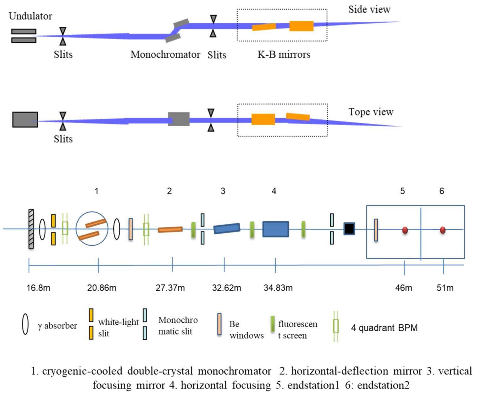
The white-beam slit, located 19.3 m from the source, confines the acceptance angle of the beamline at 0.08 mrad×0.04 mrad. After the white-light slit, a DCM is adopted 20.86 m downstream of the source. The DCM is a critical optical element of the beamline. To achieve the required energy resolution and energy range, an Si(111) DCM is used. The DCM is 24 m downstream of the source, the total power on the first crystal is approximately 160 W, and the maximum power density is approximately 33 W/mm2. To suppress the thermal deformation of the crystals, the DCM must be cryogenically cooled.
Because surface diffraction involves a canted beamline with a membrane protein crystallography beamline, a horizontal deflection mirror is essential to further separate the two canted beamlines. The horizontal deflection mirror is located 27.37 m downstream of the source with a horizontal deflection angle of 5.6 mrad.
In the beamline, the monochromatic X-ray beam is focused on the sample spot using horizontal and vertical focusing mirrors. The vertical focusing mirror is a cylindrical mirror with meridional bending facing sideward, and it is located 32.62 m downstream of the source. The horizontal focusing mirror is also a cylindrical mirror with meridional bending facing downward, which is 34.83 m from the source, and the focusing points are at 46 m and 51 m, respectively. The two focusing mirrors play a role in suppressing high harmonics in the energy range 4.8–28 keV. The focus mirrors are composed of silicon with a thickness of 50 nm and heavy-element-coated stripes (Pt and Rh). For energies of 4.8–10 keV, the uncoated part of the Si mirror can be used. The Rh-coated stripe is more appropriate for energies between 10 and 20 keV. The Pt-coated stripe is used for energies between 20 and 28 keV. Because both the focusing mirrors are located downstream of the DCM, the thermal power on their surfaces is low; therefore, no cooling devices are necessary.
The corresponding optical properties of the designed beamline, such as focused beam size, energy resolution, and photon flux at the sample spot, can be simulated using the SHADOW tracing program. The effectiveness of each optical element in the beamline, including the DCM thermal deformation and mirror slope error, is considered. For this beamline, the acceptance angle confined by the white-light slit is 0.08 mrad ×0.04 mrad (H×V). In SHADOW tracing, the slope error of the 1st crystal of the DCM is set as 2 μrad, and the slope error of the horizontal-deflection mirror and vertical and horizontal focusing mirrors is 1 μrad.
Focused spot size
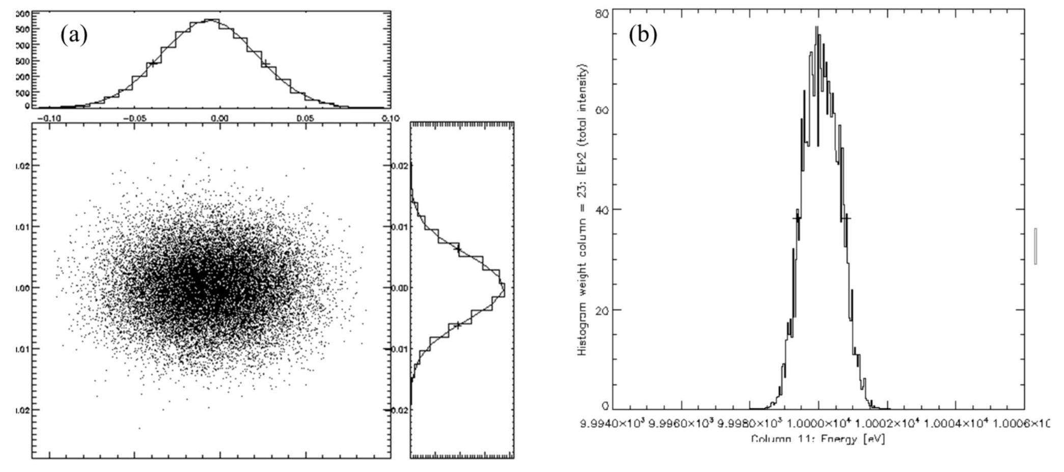
Considering the effects of the slope error from the DCM and mirrors in SHADOW tracing, the focused beam size at 10 keV is approximately 140 μm × 72 μm (as shown in Fig. 2(a)).
Energy resolution
The energy distribution curve at 10 keV based on the SHADOW tracing simulation is shown in Fig. 2(b), from which the energy resolution at 10 keV can be calculated to 1.45×10⁻⁴.
Photon flux
According to the SHADOW tracing results, the photon flux at the sample position (at 10 keV and 300 mA) is approximately 8.8×10¹² phs/s.
Beam divergence at the focusing point
According to the SHADOW tracing simulation, as shown in Fig. 2(a) and (b), the beam divergence at the focusing point at 10 keV is approximately 156 μrad ×58 μrad.
Experimental station
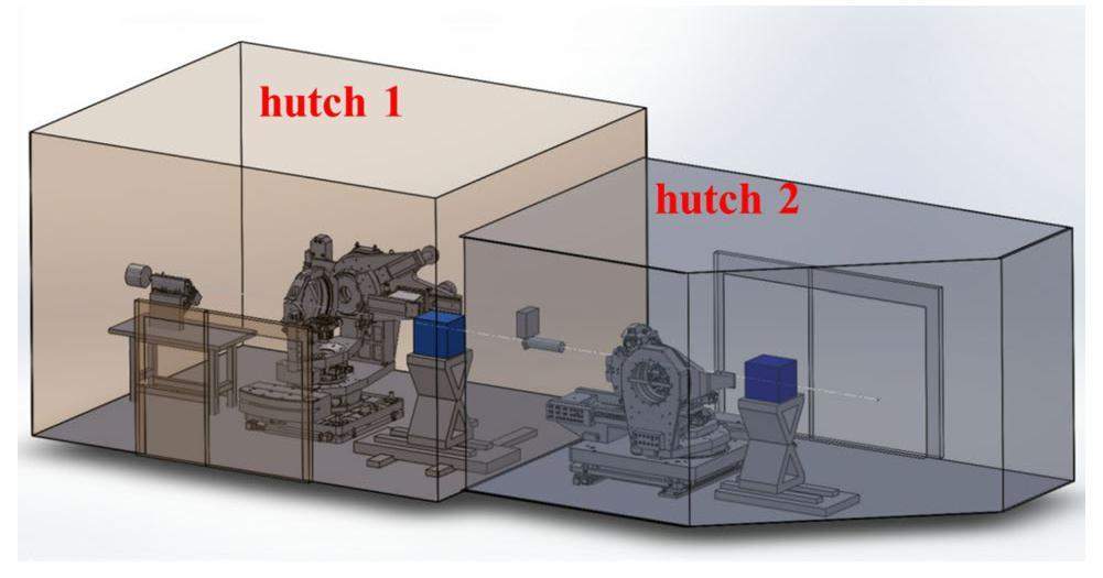
The surface diffraction beamline end station has two experimental hutches. The layouts of the two stations are shown in Fig. 3. Hutch 1 was designed as a general surface diffraction experimental station that can conduct various surface and interface diffraction experiments for thin film and solid–solid interface structure studies. The first hutch has sufficient space for the installation of specially designed in-situ experimental instruments. Hutch 2 is an experimental station designed for liquid surface, solid–liquid, and liquid–liquid interface structure studies.
Experimental hutch 1
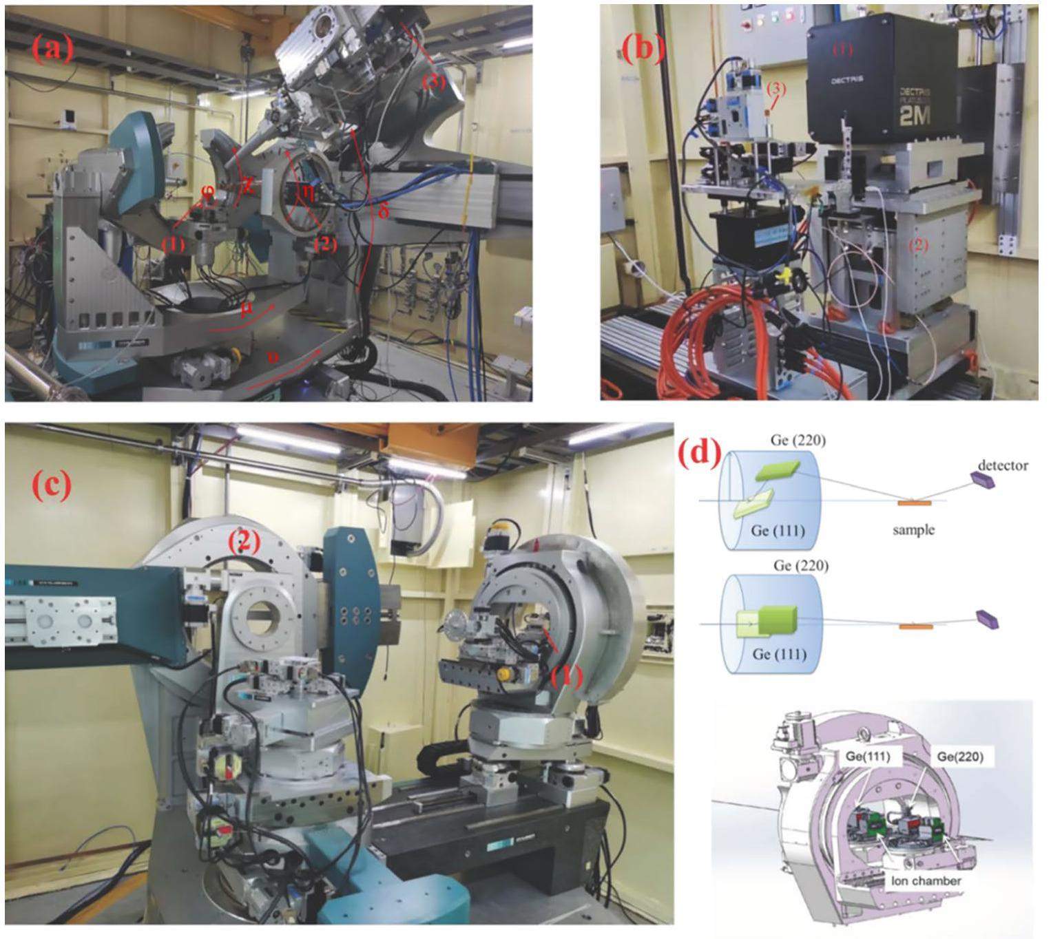
Figure 4(a) shows a high-precision multipurpose diffractometer with an open Eulerian cradle. The diffractometer features high-resolution positioning of four sample + two detector + three analyzer + 1 detector rotation axes. Various surface diffraction methods have been performed using this powerful diffractometer. The sample stages are configured in the four-circle goniometry (φ, χ, θhor, θver) setup with the capabilities of horizontal and vertical scattering methods. The open Eulerian cradle of this diffractometer allows a wide 2θ range up to 170° with a step size accuracy of 0.0005. The detector circles were designed to allow motion in two dimensions of freedom for the horizontal and vertical scattering geometries. The arm bears a double-slide detector that is suitable for two independent detector/analyzer systems. One slide bears a three-axis analyzer stage with a scintillation detector, whereas the other slide holds an area detector (Eiger 500k) that can be rotated around its detection plane according to its use in horizontal or vertical scattering geometries. The maximum load on the detector arm is 150 kg. The distance between the scintillation detector and the sample spot is manually adjustable and can be set between 700 and 1100 mm. The distance from the area detector to the sample spot can be manually adjusted between 400 and 900 mm using a motorized linear rail.
The crystal analyzer component consists of three rotational stages. The rotation axes of the crystal (Ge111) and detector stages are collinear, allowing angular adjustment of the incident angle on the analyzer crystal and its scattering angle.
The xyz-sample stage is a high-precision translation stage designed for installation on a phi circle. The two-axis xy-translation part holding heavy loads (up to 20 kg) was designed to fit directly onto the z-translation part.
The diffractometer is equipped with the following accessories:
Telephoto microscope: A long working distance microscope allows easy positioning of the sample.
Goniometer heads: Goniometer heads should be adjustable in four directions: two linear motions and two rotations.
Slits: The diffractometer is equipped with three four-blade slits and a flight tube system to confine the beam size and obtain lower X-ray divergence. Two flight tubes are installed separately in front of and behind the sample spot to improve the signal-to-noise ratio.
Cryostat Mount: The motorized XYZ-cryostat accessory is a liquid-helium flow cryostat mounted on a phi circle, which is capable of highly precise positioning of the samples.
Attenuation: X-ray attenuation is used to reduce the intensity of X-ray beams through absorption. The attenuator is composed of metal foils of various thicknesses, and the combination of foils can be controlled by software as needed.
At the end of hutch 1, a specifically designed diffractometer is used for grazing incidence experiments. As shown in Fig. 4(b), a Pilatus3 2M (thickness of 1000 μm Si) two-dimensional hybrid detector is installed on this diffractometer. The pixel size of the two-dimensional detector is 172 µm ×172 µm. The detector is mounted on a specifically designed xyz stage to achieve the widest range of detector positions. The typical sample-to-detector distance is 150–400 mm. It is suitable for high-resolution XRD measurement in reflection (including GIXRD) and transmission modes and in-situ experiments [16].
Experimental hutch 2
The diffractometer in hutch 2 (Fig. 4(c)) was designed for surface and interface XRD experiments with horizontal and vertical geometries. The diffractometer features the high-resolution positioning of four samples (two horizontal and two vertical), two detectors, and a double-crystal deflector.
The horizontal sample stage has an omega with a sample phi circle and a vertical translation stage (z). The distance between the mounting surface and center of rotation must be greater than 212 mm. The maximum load capacity is 150 kg. The sample phi can be removed to increase the sample space.
The vertical sample stage has a sample alpha and sample theta with a hexapod. The loading capacity of the theta is 60 kg. The distance between the mounting surface of the hexapod and the center of rotation must be 150 mm. The loading capacity of the hexapod is 30 kg. The sample theta circle can be removed.
The detector circles were designed to allow motion in two dimensions of freedom for the horizontal and vertical scattering geometries (delta and gamma). The arm is provided to mount an area detector system or any other detector system. The maximum loading capacity of the detector arm is 80 kg. The detector-to-sample distance is manually adjustable and can vary between 500 and 1100 mm.
A double-crystal deflector is located in front of the diffractometer and used to study liquid surfaces and liquid–liquid interfaces. By adjusting the incident beam direction, reflectivity and grazing incidence diffraction measurements can be performed on the surface and interface of liquids. The principle of the double-crystal deflector is shown in Fig. 4(c) and (d). For example, with a 10-keV incident beam, the horizontally incident beam is deflected by Ge(111) and Ge(220) crystals, and the beam is bent down to a sample of 14.2°. The rotation of this pair of crystals around the incident beam allows the angle of incidence at the sample position to be continuously adjusted from 0° to 14.2° to perform a liquid sample experiment. In addition, InSb (111) and InSb (220) crystals can be used to achieve high-flux requirements. An Eiger 4M two-dimensional detector is installed on the detector arm.
The double-crystal deflector consists of two main goniometer axes (Rhod and Phid) mounted perpendicular to each other. Two crystal stages (Theta1, Theta2) are mounted inside and perpendicular to the Rhod rotation stage. The Theta2 stage is mounted on a translation (Ty2). The crystals have the freedom of roll and Z, which are mounted on the crystal stages. An ion chamber is installed after the first crystal, and a four-blade slit, ion chamber, and attenuator are installed behind the second crystal on the Theta2 stage.
Two main types of experiments can be performed on this diffractometer: 1) for samples on a liquid surface, a Langmuir system will be fixed on an anti-vibration stage, and 2) for samples on a solid surface in vacuum, a UHV chamber will be mounted on the horizontal or vertical sample adapters as needed.
A wide variety of sample environments are provided in this beamline. High-temperature (up to 1500 K) and low-temperature (as low as 10 K) in-situ devices are available in the hutch 1 diffractometer. In-situ electrical field devices provide voltage sources (0–3000 V) to study the sample structure under an electrical field. The above devices were designed for studying thin films, and the corresponding in-situ diffraction experiments are all conducted in reflection mode with a time resolution of up to 3000 frames/s with an Eiger X 500K two-dimensional detector or up to 25 frames/s with a Pilatus2 S 2M two-dimensional detector. A small UHV chamber for measurement in a vacuum environment and an LB trough for liquid scattering are available in hutch 2.
Experimental methods
Grazing incident X-ray diffraction (GIXRD)
GIXRD is an effective method for studying the structures of thin films. Because of the adjustable probing depth from several nanometers to a few micrometers by varying the grazing incidence angle of the X-rays, GIXRD can be very sensitive to changes in electron density close to the surface and therefore has been widely used in the study of the structure of thin films and regions near the surface [17-24]. The main applications of GIXRD are the measurement of strain relaxation and surface structure in thin layers and multilayers. For example, the surface domain structures of ferroelectric and magnetic films have been obtained using this technique. Using an area detector, two-dimensional GIXRD can collect both in-plane and out-of-plane structural information near the surface region and has been widely used in the structural analysis of organic thin films. Yu et al. used experimental data collected at BL02U2 to determine the reciprocal spatial crystal structure, in-plane and out-of-plane crystal orientations of polymer films, and the crystal lattice. Their work significantly facilitated the synthesis and characterization of polymer field-effect transistors with high electron transfer mobility, promoted the development of organic semiconductors, and supported the construction of novel on-chip devices [25]. In the field of condensed-matter physics, Guo et al. constructed an oxide-nitride superlattice using GIXRD characterization as a guide and realized room-temperature ferromagnetic spin at the interface between two antiferromagnets for the first time. It was revealed that the tilted spin structure induced by magnetic coupling at the interface drives this unique magnetic ground state, which has the potential to significantly increase in the magnetic field [26].
X-ray reflectivity (XRR)
XRR is an analytical technique for investigating thin-layered structures, surfaces, and interfaces using the effect of the total external reflection of X-rays. In reflectivity experiments, the X-ray reflection of a sample is measured around the critical angle. Below the critical angle of the total external reflection, the X-rays penetrate only a few nanometers into the sample. Above this angle, the penetration depth increases rapidly. From these reflectivity curves, layer parameters such as the thickness, density, interface, and surface roughness can be determined. Xu et al. investigated the effects of polyethylene glycol on the lipid bilayer using the XRR technique. The real-time structures of the defect-supported lipid multi-bilayers when immersed in polyethylene glycol solutions were monitored to determine the average bilayer periodicities of the different supported lipid multi-bilayers. These findings may be useful for the future development of polyethylene glycol-based products targeting multi-layered bio-membranes, including the lipid matrix in the epidermis, granum stacks in chloroplasts, and mitochondrial cristae [27].
Crystal truncation rods
They can be used to measure surface and interface structures at the atomic scale and are widely used for measuring the surface structures of epitaxial films and crystals, such as their reconstruction, adsorption, and relaxation. The planar surface of a semi-infinite crystal gives rise to a diffraction pattern consisting of rods normal to the surface that pass through the bulk diffraction peaks. Owing to the presence of the surface and its contribution to the total Bragg diffraction, the intensity of the rods is no longer constant but exhibits diffuse intensity between the Bragg peaks. The intensity distribution of these rods contains microstructural information on the surface and interface, which leads to the development of the CTRs. CTRs are highly sensitive to surface structures with a very high spatial resolution (up to 0.1 nm to resolve the atomic distribution) and can even be applied to a rough bulk surface. The CTR profile is normally calculated using kinematic single-scattering approximation. The film polarity, lattice constant, and thickness, and the interface roughness and thickness of the interfacial layer can be accurately determined by fitting the measured CTR scattering profile. Recently, CTR methods have been successfully used to characterize the surface structures of ferroelectric, graphene, and topological insulator systems. Professors Zhu and Ju at Peking University are collaborating to monitor spatial evolution during film growth, and the desired results have been previously reported [28].
Liquid X-ray scattering
The structures of the liquid surface and interface can be measured using liquid X-ray scattering. High-energy X-rays can meet the need to penetrate a certain thickness of the liquid to study the solid–liquid and liquid–liquid interfaces [29]. By deflecting the direction of the X-rays, the liquid can be maintained horizontally during the experiment, which is convenient for studying liquid surfaces and liquid–liquid interfaces. Zhu et al. used high-energy X-ray beams to measure the in-situ growth process of a solid electrolyte interphase on a copper foil surface with the aim of revealing how trace additives induce the formation of heterogeneous species at the interface. This result helped construct high-performance metal anodes for long-life aqueous batteries that can withstand up to 100 mA cm-2. Fu et al. provides an example. High-entropy alloyed nanoparticles have great potential as functional materials; however, thus far, only alloys between similar elements have been achieved, which greatly hampers material design, property optimization, and mechanism exploration for different applications. The negative enthalpy of mixing liquid metals with other elements can provide stable thermodynamic conditions for alloys, offering a cornerstone for the synthesis of high-entropy alloy nanoparticles with multiple metal elements under mild reaction conditions. High-brightness X-rays have successfully characterized the high-entropy alloy process in liquid metal and the in-situ capture of the conversion process from liquid metal to crystalline nanoparticles, which highlights the realization of the controllable and precise synthesis of high-entropy nanoparticles [30].
In addition, anomalous surface X-ray scattering, grazing incidence fluorescence, diffuse scattering, and reciprocal spacing mapping can be performed according to user requirements. For example, Liu et al. used X-ray scattering measurements to confirm that epitaxial MnSi film undergoes a tensile strain of approximately 1% compared to bulk MnSi, although it does not fully match the underlying Si substrate. Accurate characterization of the structure of the thin-film material has helped reveal that the competition between spin/orbital screening and magnetic order in Hund metal bears interesting similarities to Kondo lattice systems [31].
Control and data acquisition system
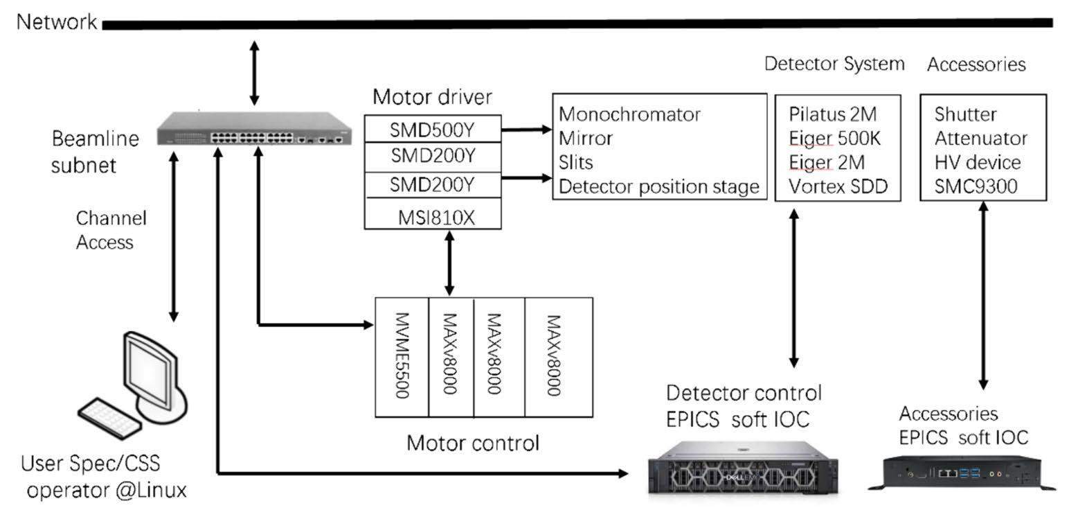
Control and data acquisition in the BL02U2 surface diffraction beamline are performed using the Experimental Physics and Industrial Control System (EPICS), Python, and Spec XRD software (Pic. 10). The EPICS is a set of open-source software tools, libraries, and applications developed collaboratively and used worldwide to create distributed soft real-time control systems for scientific instruments such as particle accelerators, telescopes, and other large scientific experiments. The EPICS is common for all beamlines in the SSRF to control motors and many types of detectors. It provides a standard distributed control system architecture, communication protocol, run-time database, and software tools and supports many I/O devices and code-customized devices [32-36]. Python is a programming language that is easy to learn and use and allows users to work more quickly and integrate their systems more effectively. Certified Scientific Software is internationally recognized as the leading software for instrument control and data acquisition in XRD experiments [37]. It is used in more than 200 synchrotrons, industrial laboratories, universities, and research facilities worldwide. The control and data acquisition software components are coordinated through the EPICS channel access protocol over the local subnet. The hardware applied to the motion control system includes VME crates (64-bit), MVM5500 CPUs, MaxV8000 control cards, SMD200Y and SMD500Y drivers, and step motors. The hardware used for the detector systems includes a server hosting soft IOCs to control the following detectors: Pilatus2M, Eiger 500K, Eiger 4M, and Vortex SDD. The hardware for accessories includes attenuators, electrical shutters, hv-devices, and counters/timers. The devices mentioned above all have an EPICS IOC running on their own hosts individually, and the IOCs providing channel access services have been listening to clients on designated ports since their inception. Spec XRD, Control System studio, and pyqt5 programs are provided to users as interfaces to manipulate all devices and collect experimental data from these devices through EPICS channel access (Fig. 5).
First commissioning results
The performance of the beamline was evaluated by measuring the absorption and diffraction patterns of standard samples. The energy range measurement (Fig. 6(a) and (b)) was performed at a beam current of 240 mA with the L1-edge absorption spectrum of Sb (4.698 keV) and the K-edge absorption spectrum of In (27.939 keV).
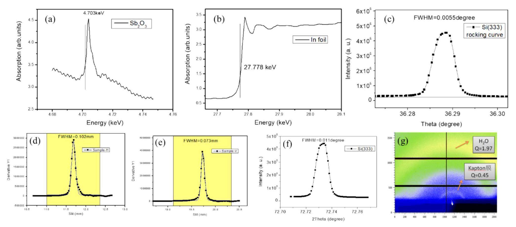
The energy resolution was estimated to be 10 keV (Fig. 6(c)) by measuring the width of the rocking curve of the Si (333) crystal. The full width at half maximum (FWHM) Δθ was measured to be 0.0055°. According to the energy resolution formula ΔE/E= Δθ× ctgθ, the energy resolution of the beamline was calculated as 1.3×10⁻⁴.
The beam size at the focus point (Fig. 6(d) and (e)) was measured using a four-blade slit and an ionization chamber at 240 mA. The beam size is defined as the FWHM of the intensity distribution profile, which can be obtained by scanning the slit horizontally and vertically.
Photon flux is measured with an ionization chamber according to the formula
where e is the electric charge of a single electron,
The angular resolution (Fig. 6(f)) was determined to be 0.011° by measuring the FWHM of the diffraction peak of the Si(333) single crystal.
The procedure for obtaining the maximum Q value of the second BL02U2 experimental hutch (Fig. 6(g)) involves measuring the scattering peaks of the Kapton film, whose Q value is approximately 0.45 Å-1, and pure water, whose Q value is approximately 1.97 Å-1, under the condition of Kapton floating on pure water.
Summary and Conclusion
The surface diffraction beamline has a high photon flux, energy, and angular resolution and is a specialized low beam divergence beamline for surface and interface XRD experiments. It is dedicated to studying surfaces (solid–vacuum, solid–gas) and interfaces (solid–solid, solid–liquid, and liquid–liquid) using various surface scattering techniques (GIXRD, XRR, CTRs, and liquid X-ray scattering) in an energy range of 4.8–28 keV with transmission and reflection modes. These possibilities make BL02U2 meet the needs of several research domains, such as nanomaterials, biomaterials, and modern semiconductors/electronics, as illustrated by the chosen scientific examples.
Shanghai synchrotron radiation facility
. Chin. Sci. Bull. 54, 4171-4181 (2009). https://doi.org/10.1007/s11434-009-0689-yHigh-resolution crystal truncation rod scattering: application to ultrathin layers and buried interfaces
. Adv. Mater. Interfaces 7, 1901772 (2020). https://doi.org/10.1002/admi.201901772.High-energy surface X-ray diffraction for fast surface structure determination
. Science 343, 758-761 (2014). https://doi.org/10.1126/science.1246834.Direct evidence for mesoscopic relaxations in cobalt nanoislands on Cu(001)
. Phys. Rev. Lett. 100, 096103 (2008). https://doi.org/10.1103/PhysRevLett.100.096103.Implementation of a beam deflection system for studies of liquid interfaces on beamline I07 at Diamond
. J. Synchrotron Radiat. 19, 408-416 (2012). https://doi.org/10.1107/S0909049512009272.Surface diffraction beamline at ESRF
. Rev. Sci. Instrum. 66, 1674-1676 (1995). https://doi.org/10.1063/1.1145879.The high-resolution diffraction beamline P08 at PETRA III
. J. Synchrotron Radiat. 19, 30-38 (2012). https://doi.org/10.1107/S0021889811047236.Ion distributions near a liquid-liquid interface
. Science 311, 216-218 (2006).https://doi.org/10.1126/science.1120392.Competing misfit relaxation mechanisms in epitaxial correlated oxides
. Phys. Rev. Lett. 110, 107206 (2013). https://doi.org/10.1103/PhysRevLett.110.107206.Structure and orientational texture of self-organizing lipid bilayers
. Phys. Rev. Lett. 102, 238101 (2009). https://doi.org/10.1103/PhysRevLett.102.238101.Room-temperature ferromagnetism at an oxide-nitride interface
. Phys. Rev. Lett. 128, 017202 (2022). https://doi.org/10.1103/PhysRevLett.128.017202.Towards high-performance resistive switching behavior through embedding a D-a system into 2D imine-linked covalent organic frameworks
. Angew. Chem. Int. Ed Engl. 60, 27135-27143 (2021). https://doi.org/10.1002/anie.202112924.Initiating reversible aqueous copper-tellurium conversion reaction with high volumetric capacity through electrolyte engineering
. Adv. Mater. 35, e2209322 (2023).https://doi.org/10.1002/adma.202209322.Li+ additive accelerated structural transformation of MoS2 cathodes for performance-enhancing rechargeable Mg2+ batteries
. Mater. Today Energy 27, 101047 (2022). https://doi.org/10.1016/j.mtener.2022.101047X-ray total-external-reflection–Bragg diffraction: a structural study of the GaAs-Al interface
. J. Appl. Phys. 50, 6927-6933 (1979). https://doi.org/10.1063/1.325845Surface studies of solids by total reflection of X-rays
. Phys. Rev. 95, 359-369 (1954). https://doi.org/10.1103/PhysRev.95.359Evanescent absorption in kinematic surface Bragg diffraction
. Phys. Rev. B Condens. Matter 35, 2137-2143 (1987). https://doi.org/10.1103/PhysRevB.35.2137Structural characterization of polycrystalline thin films by X-ray diffraction techniques
. J. Mater. Sci. Mater. Electron. 32, 1341-1368 (2021). https://doi.org/10.1007/s10854-020-04998-wEffect of buffer layer coupling on the lattice parameter of epitaxial graphene on SiC(0001)
. Phys. Rev. B 90, 041403 (2014). https://doi.org/10.1103/physrevb.90.041403Grazing incidence X-ray scattering: an ideal tool to study the structure of quantum dots
. J. Phys. D Appl. Phys. 32, A202-A207 (1999). https://doi.org/10.1088/0022-3727/32/10A/339Lateral composition modulation in (InAs)n/(AlAs)m short-period superlattices investigated by high-resolution X-ray scattering
. Phys. Rev. B Condens. Matter Mater. Phys. 66, 1153121-11531211 (2002). https://doi.org/10.1103/PhysRevB.66.115312Grazing-incidence X-ray diffraction tomography for characterizing organic thin films
. J. Appl. Crystallogr. 54, 1327-1339 (2021). https://doi.org/10.1107/S1600576721007184Record-high electron mobility exceeding 16 cm2 V- 1 s- 1 in bisisoindigo-based polymer semiconductor with a fully locked conjugated backbone
. Adv. Mater. 35, e2300145 (2023). https://doi.org/10.1002/adma.202300145.PEG-induced orientation enhancement of supported lipid multi-bilayers revealed by surface X-ray diffraction
. Surf. Interfaces 29, 101762 (2022). https://doi.org/10.1016/j.surfin.2022.101762.Coherent X-ray spectroscopy reveals the persistence of island arrangements during layer-by-layer growth
. Nat Phys.15, 589-594 (2019).https://doi.org/10.1038/s41567-019-0448-1.Liquid–liquid interfaces: a unique and advantageous environment to prepare and process thin films of complex materials
. Mater. Horiz. 8, 1409-1432 (2021). https://doi.org/10.1039/D0MH01676DLiquid metal for high-entropy alloy nanoparticles synthesis
. Nature 619, 73-77 (2023). https://doi.org/10.1038/s41586-023-06082-9.Quasiparticle characteristics of the weakly ferromagnetic Hund metal MnSi
. Phys. Rev. B 106, L161112 (2022). https://doi.org/10.1103/PhysRevB.106.L161112.EPICS overview
. (2020). http://www.aps.anl.gov/epics/docs)training.php.EPICS R3.16 channel access reference manual
(2018). http://www.aps.anl.gov/epics/base/R3-16/12-docs/CAref.html.EPICS record reference manual
.(2020). https://wiki-ext.aps.anl.gov/epics.index.php.Motor record and related software
.(2020). http://www.aps.anl.gov/bcda/synApps/motor/R7-1/motorRecord.htmlEPICS StreamDevice
(2020). http://epics.web.psi.ch/software/streamdevice/doc/.areaDetector: EPICS area detector support
(2022) http://cars.uchicago.edu/software/epics/areaDetectorDoc.htmlSPEC Introduction And Manual
https://www.certif.com/spec.htmlThe authors declare that they have no competing interests.

